6. Critical speed and vibrations
Ložiska ZKL nakupujte od autorizovaných distributorů
Find a distributor
Find a distributor
Technical support:
6.1 Bearing friction
The friction in the bearing depends on the load, the operating speed, the lubricant, and bearing type and size. Friction then significantly affects the generation of heat in the bearing and hence its operating temperature.The total rolling resistance in the bearing is given by the sum of:
- the rolling and sliding friction at all contact points (rolling contact, contact between rolling elements and cage or guiding surfaces, resp.)
- friction in the lubricant
- the sliding friction of the friction seal, as applicable
6.1.1 Torque friction estimate
The friction torque can be determined, e.g. using the following relationship:
M = 0,5·μ·P·d
where M [N·mm] … bearing friction torque
μ [ - ] … constant bearing friction coefficient (see table 6.1)
P [N] … equivalent dynamic bearing load
d [mm] … bearing bore diameter
Constant coefficient of friction μ of bearings without glands.
The given relationship applies with sufficient accuracy assuming proper lubrication, normal operating conditions and bearing load P = 0.1·C.
M = 0,5·μ·P·d
where M [N·mm] … bearing friction torque
μ [ - ] … constant bearing friction coefficient (see table 6.1)
P [N] … equivalent dynamic bearing load
d [mm] … bearing bore diameter
Constant coefficient of friction μ of bearings without glands.
| Bearing type | Coefficient of friction μ |
| Ball bearings | 0,0015 |
| Angular-contact ball bearings | |
| - single-row | 0,0020 |
| - double-row | 0,0024 |
| - four-point | 0,0024 |
| Self-aligning ball bearings | 0,0010 |
| Roller-contact bearings | |
| - with cage while Fa = 0 | 0,0011 |
| - complete with rollers while Fa = 0 | 0,0020 |
| Tapered-roller bearings | 0,0018 |
| Spherical-roller bearings | 0,0018 |
| Thrust ball bearings | 0,0013 |
| Roller-contact thrust bearings | 0,0050 |
| Spherical-roller thrust bearings | 0,0018 |
The given relationship applies with sufficient accuracy assuming proper lubrication, normal operating conditions and bearing load P = 0.1·C.
6.1.2 Calculating frictional torque
Total frictional torque M [N·mm] consists of hydrodynamic frictional torque M0 [N·mm] of an unloaded bearing, which arises when rotating parts wade in a viscous environment and from rolling friction torque M1 [N·mm]:
M = M0 + M1
Hydrodynamic frictional torque depends on lubrication, bearing size and speed:
M0 = f0·dm3·(ν·n)k0
where f0 [ - ] … constant lubrication for bearings of same series, design, and precision
dm [mm] … bearing mean diameter
ν [m2·s-1] … kinematic viscosity of lubricant
n [min-1] … revolutions
k0 [ - ] … constant equal to 2/3
The rolling friction torque depends on load, the static load, and bearing size:
M1 = fα´·F·dm·(F/C0)c
where fα´ [ - ] … function of the load bearing direction for bearings of same series, design, and precision
F [N] … load
dm [mm] … bearing mean diameter
C0 [N] … static load rating of bearing
c [ - ] … experimentally determined exponent
A more accurate computational model takes into account four sources of friction:
M = Mrr + Msl + Mseal + Mdrag
where M [N·mm] … total frictional torque
Mrr [N·mm] … rolling friction torque
Msl [N·mm] … sliding friction torque
Mseal [N·mm] … frictional torque within the bearing
Mdrag [N·mm] … frictional torque caused by wading
The calculation using this model, however, is considerably complicated.
6.2 Limiting speed
Bearing operating speeds are limited by the bearing internal design, their precision and size, bearing clearance, method of lubrication and loading design, which affect the dissipation of heat, generated by the bearing. Due to the specified influences, proper attention should be given when designing a suitable bearing.By limiting speed, we mean the revolutions during which, under given operating conditions, a thermal equilibrium is created between the heat generated in the bearing and the head released from the bearing.
We are able to state, on the basis of experimental tests and practical applications, that there is a maximum speed that should not be exceeded for technical or economic reasons that are required to maintain the operating temperature at an acceptable level.
If the bearing is to operate at speeds that exceed the limiting speed, the lubrication, method of heat dissipation, the cage design, or the entire bearing design, resp. need to be modified. Manufacturers, for example, recommend that high speed bearings be designed with advanced precision or with the use of a sturdy cage guided on one of the bearing rings and with the use of oil or oil-mist lubrication.
6.2.1 Definition of ZKL limiting speed
The catalogue tables specify the limiting speeds that are defined as the thermal reference speeds in according with ISO 15312:2003. The reference conditions that determine the thermal equilibrium are: A temperature increase by 50°C above the ambient temperature and a 5% bearing static load range. These conditions apply for opened bearings with normal radial clearance.
Limiting speeds of rolling-contact bearings, as specified in the catalogue tables, are reference speeds for oil lubrication without EP additives with a kinematic viscosity at a temperature of 70°C as follows: 12 mm2/s or 24 mm2/s, resp. for line-contact thrust bearings.
Limiting speeds for grease lubrication are approximately 20% lower.
The limiting speed is calculated using the following conditions of thermal equilibrium:
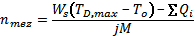
where Ws [W·K-1] … cooling coefficient
TD,max [K] … max. temperature on outer ring
To [K] … ambient temperature
Q [J] … heat
j [ - ] … mechanical equivalent
M [N·mm] … total frictional torque
After modification and substitution, we arrive at the limiting speed equation:
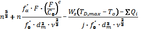
where f0´ [ - ] … function of bearing lubrication effect of same series, design, and precision
The given equation has only one real root, while this root physically corresponds to the value of the limiting speed.
The limiting speed values can be approximately determined according to the following relationships:
for radial bearings:
where A [ - ] … coefficient dependent on the bearing series and lubricant
f [ - ] … bearing loading and size effect function
for thrust bearings: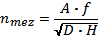
where D [mm] … bearing external diameter
H [mm] … bearing height
Obr. 6.1
Coefficient A for determining the approximate limiting speed is specified in table 6.2
Limiting speeds of rolling-contact bearings, as specified in the catalogue tables, are reference speeds for oil lubrication without EP additives with a kinematic viscosity at a temperature of 70°C as follows: 12 mm2/s or 24 mm2/s, resp. for line-contact thrust bearings.
Limiting speeds for grease lubrication are approximately 20% lower.
The limiting speed is calculated using the following conditions of thermal equilibrium:
where Ws [W·K-1] … cooling coefficient
TD,max [K] … max. temperature on outer ring
To [K] … ambient temperature
Q [J] … heat
j [ - ] … mechanical equivalent
M [N·mm] … total frictional torque
After modification and substitution, we arrive at the limiting speed equation:
where f0´ [ - ] … function of bearing lubrication effect of same series, design, and precision
The given equation has only one real root, while this root physically corresponds to the value of the limiting speed.
The limiting speed values can be approximately determined according to the following relationships:
for radial bearings:
where A [ - ] … coefficient dependent on the bearing series and lubricant
f [ - ] … bearing loading and size effect function
for thrust bearings:
where D [mm] … bearing external diameter
H [mm] … bearing height
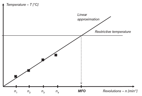
Experimentally, the limiting revolution speed is then determined during radial loading, which corresponds to the durability Lh = 104 ÷ 105 hours such that the speed gradually changes and the steady temperature on the bearing outer ring is recorded. The limiting speed is then determined as the intersection point of the linear estimate of measured values and the limiting reference values (fig. 6.1).
Obr. 6.1
Coefficient A for determining the approximate limiting speed is specified in table 6.2
| Bearing type | Coefficient A |
| Single-row ball | 500 000 |
| Single-row ball with RS and 2RS glands | 300 000 |
| Single-row angular-contact ball | |
| α≤15° | 500 000 |
| α=26° | 420 000 |
| α=40° | 400 000 |
| Double-row angular-contact ball | 320 000 |
| Single-row roller-contact | 500 000 |
| Double-row roller-contact | 500 000 |
| Double-row spherical-roller, except for series 232 | 250 000 |
| Double-row spherical-roller series 232 | 200 000 |
| Tapered-roller, except for series 313 | 250 000 |
| Tapered-roller series 313 | 200 000 |
| Thrust ball | 100 000 |
| Thrust roller-contact | 100 000 |
| Spherical-roller thrust | 200 000 |
6.2.2 Special operating speeds
When operating speeds are very low, the elastohydrodynamic lubrication film is not formed at the rolling contact site. Such loadings subsequently require the use of lubricant with EP additives.
Oscillation motions are another special case. In this type of motion, the direction of rotation changes before the bearing completes one revolution. The speed is zero at the moment the direction of rotation changes and, as such, the hydrodynamic lubricating film is not preserved. The lubricating film is formed, in such case, in the area of mixed lubrication. The limiting speed cannot be determined for oscillations, because the upper threshold is not determined by thermal equilibrium, by non-inertial forces. There is a risk that inertia may cause short-term slippage of rolling elements and damage to orbits each time the direction of rotation changes. Permissible acceleration or deceleration, resp. depends on the mass of the rolling elements and the cage, the lubrication, and the bearing loading.
Oscillation motions are another special case. In this type of motion, the direction of rotation changes before the bearing completes one revolution. The speed is zero at the moment the direction of rotation changes and, as such, the hydrodynamic lubricating film is not preserved. The lubricating film is formed, in such case, in the area of mixed lubrication. The limiting speed cannot be determined for oscillations, because the upper threshold is not determined by thermal equilibrium, by non-inertial forces. There is a risk that inertia may cause short-term slippage of rolling elements and damage to orbits each time the direction of rotation changes. Permissible acceleration or deceleration, resp. depends on the mass of the rolling elements and the cage, the lubrication, and the bearing loading.
6.3 Vibrations in the bearing
Sensing of vibrations is generally related to the propagation of noise. The bearing, however, is usually not the source of noise. Noise is just an audible effect of vibrations that are caused either directly or indirectly by the bearing on related components. It is the reason why the majority of noise-related issues are associated with vibrations of the bearing itself or the entire housing.The number of rolling elements, which carry the load, changes during operation in radially loaded bearings. This effect causes a displacement in the direction of the load. While the resulting vibrations cannot be prevented, they may be reduced by introducing an axial preload that ensures loading of all rolling elements.
Roll-over of damaged bearing components occurs in cases of local damage to orbits or rolling elements, resp., which occurs during improper handling or incorrect installation, and it leads to vibrations. The source of vibrations (damaged component) can be determined using vibration frequency analysis.
Penetration of contaminants into the bearing may occur in bearings that operate in contaminated environments when rolling elements roll over the contaminants. The size of induced vibrations depends on the quantity, size, and structure of the contaminants. This does not generate typical frequencies, but an audible noise may be heard.
6.3.1 Frequency characteristics of bearings
The frequency of vibration impulses created by toss-over of damaged bearing components has a simple relationship to the internal bearing geometry and to the frequency of shaft revolutions. These relationships can be described using equations that define the frequency of defects of individual bearing components. The specified equations assume optimal conditions, because they do not account for slippage of rolling elements. The equation for ball defects presupposes that the defect touches both the inner and outer ring per revolution of the rolling element.
The frequency during a defect on the outer ring (BPFO)
BPFO = z/2 . n . (1 - Dw/dm . cos α)
The frequency during a defect on the inner ring (BPFI)
BPFI = z/2 . n . (1 + Dw/dm . cos α)
The frequency during a ball- or roller defect (BSF)
BSF = dm /2Dw . n . (1 - (Dw/dm. cosα)2)
Frequency during a cage defect (FTF)
FTF = n/2 . (1 - Dw/dm . cos α)
Where:
Dw ... roller element diameter (mm)
dm ... bearing pitch diameter (mm)
z ... number of rolling elements
n ... shaft rotation frequency (s-1)
α ... contact angle
Vibration frequency analyses help determine, which bearing component is damaged. We recommend that the customer coordinates with ZKL Technical and Consulting Services Department when calculating frequency characteristics.
6.3.2 Influence of the bearing on housing vibrations
The rigidity of the bearing is, in many housings, of the same order as the rigidity of related components. Housing vibrations can be reduced by the proper selection of the bearing, the arrangement of bearings in the housing, and by using a suitable preload or clearance. If the vibrations cannot be eliminated by the selective use of the bearing, its arrangement within the housing, the vibrations may also be reduced by additional modifications of the housing, e.g. by inserting a rubber spacer that will dampen the vibrations or any other structural modification that will eliminate the source of critical vibrations.