5.1 General information
A properly installed and lubricated roller-contact bearing will operate under normal conditions, i.e. absent extreme speeds and temperatures, until it fails due to fatigue of materials at acting surfaces. Repeated stress on the contact surfaces between roller-contact surfaces and rings will manifest after a certain period depending on the magnitude of load as a stress fracture. This will expand until a part of the bearing ring material or roller-contact bearing breaks off (pitting) and causes failure. Many bearings are also discarded for other reasons than material fatigue, but these failures can be avoided if the bearing is treated properly, if it is properly installed, lubricated, and overloading is avoided.When a certain number of identical bearings are tested for fatigue under specified operating conditions (load and rpm), there is a large variance of durability between individual bearings. In a group of 30 or more bearings, the ratio between the shortest and longest durability can be 20-fold or more. A durability variance curve can be drawn for each tested group of bearings that illustrates the relationship between the durability and the number of bearings, which were discarded.
The required bearing size is determined on the basis of externally acting forces and based on the durability and reliability demands of the seated bearing. The size, direction, purpose, and nature of the bearing load as well as the revolution operating speed are determinant when selecting the bearing type and size. Meanwhile, other special or important conditions of each individual case must be considered, e.g. operating temperature, spatial allowances, ease of installation, lubrication requirements, packing, etc., which can affect the selection of the most suitable bearing. Various types of bearings may, in many cases, be suitable for the given specific conditions.
In terms of the action of external forces and the function of the bearing in the respective node or unit, we distinguish two types of roller-contact bearing loads in bearing technology:
- If the bearing rings turn in relation to one another and the bearing is exposed, under such conditions, to external forces (which applies for the majority of bearing applications), we refer to this as a dynamic bearing load,
- If the bearing rings do not turn in relation to one another or turn very slowly, the bearing transmits oscillating motion, or external forces act for shorter period than the time of one bearing revolution, we refer to this as a static bearing load.
5.2 Roller-contact bearing reliability
The reliability of a group of apparently identical roller-contact bearings, operating under identical conditions, is the percentage of the group, expected to achieve or exceed the specified durability.The reliability of an individual roller-contact bearing is the probability that the bearing will achieve or exceed the specified durability.
The equation for calculating durability includes the effect of stress induced by external loads, lubrication, and surface kinematics at the site of rolling contact. Including the impact of the comprehensive system of stress on bearing durability makes it possible to better anticipate the actual manner, in which a bearing behaves within a specific housing. International standards, such as e.g. ISO 281, are based on the theory of material fatigue at the site of rolling contact. One must keep in mind that a complete bearing can be considered as a system, the individual components of which (bearing rings, rolling elements, cage, lubricant, and gland) have the same effect on durability and, in certain cases, are even a decisive factor in determining the bearing durability during operation. The optimal operating durability is theoretically achieved when all of the components achieve the same durability. In other words, the calculated durability corresponds to the actual operating durability if the operating durability of related components is at least as long as the calculated bearing durability. Related components in such case are the cage, bearing gland, and lubricant. The most important factor in practise is metal fatigue.
5.3 Dynamic Load Capacity
Dynamic load capacity is, according to ISO 281:1990, a constant invariable load that a bearing can theoretically carry at a basic durability of one million revolutions.The dynamic load capacity Cr for radial bearings relates to constant, invariable, entirely radial loads. For thrust bearings, the dynamic load capacity Ca relates to the invariable, purely axial load acting in the bearing’s axis.
The dynamic load capacity Cr and Ca, whose magnitude depends on the bearing dimensions, the number of rolling elements, the bearing material and design, is provided in the table for each bearing. The dynamic load capacity values were determined in accordance with ISO standard 280. These values are verified on testing equipment and confirmed in operating results.
The numeric values specified in this catalogue apply for chrome steel bearings, heat treated to a minimal hardness of 58 HRC and normal operating conditions. NEW FORCE bearings display, among others, improved material properties and advanced manufacturing processes. To determine the dynamic load capacity in these bearings, thus requires the use of correction factors according to ISO 281. More information about these bearings is available in separate chapter 7.7.
5.4 Durability
It is the number of revolutions that a bearing lasts, before fatigue of one of its components occurs, which manifests as flaking of material. It is expressed either as the total number of revolutions or operating hours, or in vehicles, by the distance travelled (number of driven km).
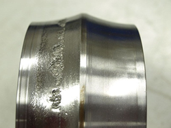 Fig. 5.1 Photo-illustration of fatigue damage on the orbit |
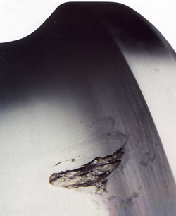 Fig. 5.2 Photo-illustration of fatigue damage on the orbit |
The material is primarily responsible for significant variance in durability in a broader range of identical bearings tested under the same conditions. No material or bearing steel is entirely homogenous and contains certain weak points. If a weak point is located on the orbit, where large load (stress) is generated, then the durability of the bearing will be small. The durability is higher where the load is decreased. Poor material has a large amount of weak points and, in all likeliness, some of them lie in areas of greatest load. The variance of durability will thus be less in poor material and larger in first-class material.
Variance of durability is also affected by manufacturing tolerances of individual components. The tolerances of roller diameters and radiuses of orbits significantly affect loads on roller-contact surfaces. For manufacturing reasons, the radial clearance in a bearing varies within a specific tolerance, and as such, it also affects the distribution of pressure on individual roller elements. The distribution of forces within the bearing in the same manner cause expansion and decrease the orbit diameter due to the prescribed placement of rings on the shaft and within the housing.
Adherence to the prescribed material composition, its purity, and heat treatment is also an important indicator of bearing quality. Large variances in durability of large quantities of identical roller-contact bearings, testing under identical conditions is but a natural consequence of the specified individual influences. Current research shows that even the quality of lubrication, its purity, and quantity may significantly impact bearing durability. Lubrication is taken into account in the modified durability calculation, see further.
The results of performed durability tests and practical operating experiences indicate that identical bearings, operating under identical conditions, do not achieve the same durability. The term “durability” must thus be correctly defined.
5.5 Basic durability equation
The basic durability of a bearing is mathematically defined by the durability equation, which applies for all types of bearings.L_10=(C/P)^p or C/P=(L_10 )^(1/p)
- L_10 - basic durability [10^6⥂rev]
- C - dynamic load capacity [kN]
- - (the Cr and Ca values are specified in the product section of the catalogue)
- P - bearing equivalent dynamic load capacity [kN]
- (the equations for calculating Pr and Pa are provided in the chapter Equivalent Dynamic Load Capacity and for each structural group of bearings)
- p - ball bearing exponent p=3
- - For roller, needle roller, spherical-roller, and tapered-roller bearings p=10/3
The basic durability of a bearing is thus understood to mean the durability that 90% of bearings achieve or exceed from a set of identical bearings, working under the same operating conditions. All standard durability calculations are performed for this reliability level. Mean durability Ls is the durability that 50% of bearing from the same set achieve; it is about 5 times higher than the basic durability. In contrast, the durability achieved by 99% of bearings is about one fifth when compared with the basic durability. The impact of the degree of reliability on the durability calculation is specified in chapter 5.6.
Table 5.1 lists the relationship of durability L10 in millions of revolutions and the corresponding C/P ratio. If the revolution speed is unchanged, then the durability can be calculated using the modified equation, which expresses the basic durability in terms of operating hours:
L_10h=(C/P)^p⋅(10^6)/(60⋅n)
L_10h - basic durability [h]
n - revolution speed [1/min]
The relationship of the C/P ratio on basic durability L10h and on the revolution speed for ball bearings is specified in table 5.2 and in table 5.3 for roller, needle, spherical-roller, and tapered-roller bearings.
| C/P ratio depending on durability L10h | |||||||
| Ball bearings | Roller, needle-roller, spherical-roller, and tapered-roller bearings | ||||||
| L10 Durability | C/P | L10 Durability | C/P | L10 Durability | C/P | L10 Durability | C/P |
| x 106rev | x 106rev | x 106rev | x 106rev | ||||
| 0,5 | 0,79 | 600 | 8,43 | 0,5 | 0,81 | 600 | 6,81 |
| 0,75 | 0,91 | 650 | 8,66 | 0,75 | 0,92 | 650 | 6,98 |
| 1 | 1,00 | 700 | 8,88 | 1 | 1,00 | 700 | 7,14 |
| 1,5 | 1,14 | 750 | 9,09 | 1,5 | 1,13 | 750 | 7,29 |
| 2 | 1,26 | 800 | 9,28 | 2 | 1,24 | 800 | 7,43 |
| 3 | 1,44 | 850 | 9,47 | 3 | 1,39 | 850 | 7,56 |
| 4 | 1,59 | 900 | 9,65 | 4 | 1,52 | 900 | 7,70 |
| 5 | 1,71 | 950 | 9,83 | 5 | 1,62 | 950 | 7,82 |
| 6 | 1,82 | 1 000 | 10,00 | 6 | 1,71 | 1 000 | 7,94 |
| 8 | 2,00 | 1 100 | 10,30 | 8 | 1,87 | 1 100 | 8,17 |
| 10 | 2,15 | 1 200 | 10,60 | 10 | 2,00 | 1 200 | 8,39 |
| 12 | 2,29 | 1 300 | 10,90 | 12 | 2,11 | 1 300 | 8,59 |
| 14 | 2,41 | 1 400 | 11,20 | 14 | 2,21 | 1 400 | 8,79 |
| 16 | 2,52 | 1 500 | 11,40 | 16 | 2,30 | 1 500 | 8,97 |
| 18 | 2,62 | 1 600 | 11,70 | 18 | 2,38 | 1 600 | 9,15 |
| 20 | 2,71 | 1 700 | 11,90 | 20 | 2,46 | 1 700 | 9,31 |
| 25 | 2,92 | 1 800 | 12,20 | 25 | 2,63 | 1 800 | 9,48 |
| 30 | 3,11 | 1 900 | 12,40 | 30 | 2,77 | 1 900 | 9,63 |
| 35 | 3,27 | 2 000 | 12,60 | 35 | 2,91 | 2 000 | 9,78 |
| 40 | 3,42 | 2 200 | 13,00 | 40 | 3,02 | 2 200 | 10,10 |
| 45 | 3,56 | 2 400 | 13,40 | 45 | 3,13 | 2 400 | 10,30 |
| 50 | 3,68 | 2 600 | 13,80 | 50 | 3,23 | 2 600 | 10,60 |
| 60 | 3,91 | 2 800 | 14,10 | 60 | 3,42 | 2 800 | 10,80 |
| 70 | 4,12 | 3 000 | 14,40 | 70 | 3,58 | 3 000 | 11,00 |
| 80 | 4,31 | 3 500 | 15,20 | 80 | 3,72 | 3 500 | 11,50 |
| 90 | 4,48 | 4 000 | 15,90 | 90 | 3,86 | 4 000 | 12,00 |
| 100 | 4,64 | 4 500 | 16,50 | 100 | 3,98 | 4 500 | 12,50 |
| 120 | 4,93 | 5 000 | 17,10 | 120 | 4,20 | 5 000 | 12,90 |
| 140 | 5,19 | 5 500 | 17,70 | 140 | 4,40 | 5 500 | 13,20 |
| 160 | 5,43 | 6 000 | 18,20 | 160 | 4,58 | 6 000 | 13,60 |
| 180 | 5,65 | 7 000 | 19,10 | 180 | 4,75 | 7 000 | 14,20 |
| 200 | 5,85 | 8 000 | 20,00 | 200 | 4,90 | 8 000 | 14,80 |
| 250 | 6,30 | 9 000 | 20,80 | 250 | 5,24 | 9 000 | 15,40 |
| 300 | 6,69 | 10 000 | 21,50 | 300 | 5,54 | 10 000 | 15,80 |
| 350 | 7,05 | 12 500 | 23,20 | 350 | 5,80 | 12 500 | 16,90 |
| 400 | 7,37 | 15 000 | 24,70 | 400 | 6,03 | 15 000 | 17,90 |
| 450 | 7,66 | 17 500 | 26,00 | 450 | 6,25 | 17 500 | 18,70 |
| 500 | 7,94 | 20 000 | 27,10 | 500 | 6,45 | 20 000 | 19,50 |
| 550 | 8,19 | 25 000 | 29,20 | 550 | 6,64 | 25 000 | 20,90 |
| C/P ratio dependent on L10h durability and rotation speed n for ball bearings | |||||||||||||||||||||||||||||
| L10h Durability | Rotation speed n [min-1] | ||||||||||||||||||||||||||||
| Hrs. | 10 | 16 | 25 | 40 | 63 | 100 | 125 | 160 | 200 | 250 | 320 | 400 | 500 | 630 | 800 | 1 000 | 1 250 | 1 600 | 2 000 | 2 500 | 3 200 | 4 000 | 5 000 | 6 300 | 8 000 | 10 000 | 12 500 | 16 000 | |
| 100 | - | - | - | - | - | - | - | - | 1,06 | 1,15 | 1,24 | 1,34 | 1,45 | 1,56 | 1,68 | 1,82 | 1,96 | 2,12 | 2,29 | 2,47 | 2,67 | 2,88 | 3,11 | 3,36 | 3,63 | 3,91 | 4,23 | 4,56 | |
| 500 | - | - | - | 1,06 | 1,24 | 1,45 | 1,56 | 1,68 | 1,82 | 1,96 | 2,12 | 2,29 | 2,47 | 2,67 | 2,88 | 3,11 | 3,36 | 3,63 | 3,91 | 4,23 | 4,56 | 4,93 | 5,32 | 5,75 | 6,20 | 6,70 | 7,23 | 7,81 | |
| 1 000 | - | - | 1,15 | 1,34 | 1,56 | 1,82 | 1,96 | 2,12 | 2,29 | 2,47 | 2,67 | 2,88 | 3,11 | 3,36 | 3,63 | 3,91 | 4,23 | 4,56 | 4,93 | 5,32 | 5,75 | 6,20 | 6,70 | 7,23 | 7,81 | 8,43 | 9,11 | 9,83 | |
| 1 250 | - | 1,06 | 1,24 | 1,45 | 1,68 | 1,96 | 2,12 | 2,29 | 2,47 | 2,67 | 2,88 | 3,11 | 3,36 | 3,63 | 3,91 | 4,23 | 4,56 | 4,93 | 5,32 | 5,75 | 6,20 | 6,70 | 7,23 | 7,81 | 8,43 | 9,11 | 9,83 | 10,60 | |
| 1 600 | - | 1,15 | 1,34 | 1,56 | 1,82 | 2,12 | 2,29 | 2,47 | 2,67 | 2,88 | 3,11 | 3,36 | 3,63 | 3,91 | 4,23 | 4,56 | 4,93 | 5,32 | 5,75 | 6,20 | 6,70 | 7,23 | 7,81 | 8,43 | 9,11 | 9,83 | 10,60 | 11,50 | |
| 2 000 | 1,06 | 1,24 | 1,45 | 1,68 | 1,96 | 2,29 | 2,47 | 2,67 | 2,88 | 3,11 | 3,36 | 3,63 | 3,91 | 4,23 | 4,56 | 4,93 | 5,32 | 5,75 | 6,20 | 6,70 | 7,23 | 7,81 | 8,43 | 9,11 | 9,83 | 10,60 | 11,50 | 12,40 | |
| 2 500 | 1,15 | 1,34 | 1,56 | 1,82 | 2,12 | 2,47 | 2,67 | 2,88 | 3,11 | 3,36 | 3,63 | 3,91 | 4,23 | 4,56 | 4,93 | 5,32 | 5,75 | 6,20 | 6,70 | 7,23 | 7,81 | 8,43 | 9,11 | 9,83 | 10,60 | 11,50 | 12,40 | 13,40 | |
| 3 200 | 1,24 | 1,45 | 1,68 | 1,96 | 2,29 | 2,67 | 2,88 | 3,11 | 3,36 | 3,63 | 3,91 | 4,23 | 4,56 | 4,93 | 5,32 | 5,75 | 6,20 | 6,70 | 7,23 | 7,81 | 8,43 | 9,11 | 9,83 | 10,60 | 11,50 | 12,40 | 13,40 | 14,50 | |
| 4 000 | 1,34 | 1,56 | 1,82 | 2,12 | 2,47 | 2,88 | 3,11 | 3,36 | 3,63 | 3,91 | 4,23 | 4,56 | 4,93 | 5,32 | 5,75 | 6,20 | 6,70 | 7,23 | 7,81 | 8,43 | 9,11 | 9,83 | 10,60 | 11,50 | 12,40 | 13,40 | 14,50 | 15,60 | |
| 5 000 | 1,45 | 1,68 | 1,96 | 2,29 | 2,67 | 3,11 | 3,36 | 3,63 | 3,91 | 4,23 | 4,56 | 4,93 | 5,32 | 5,75 | 6,20 | 6,70 | 7,23 | 7,81 | 8,43 | 9,11 | 9,83 | 10,60 | 11,50 | 12,40 | 13,40 | 14,50 | 15,60 | 16,80 | |
| 6 300 | 1,56 | 1,82 | 2,12 | 2,47 | 2,88 | 3,36 | 3,63 | 3,91 | 4,23 | 4,56 | 4,93 | 5,32 | 5,75 | 6,20 | 6,70 | 7,23 | 7,81 | 8,43 | 9,11 | 9,83 | 10,60 | 11,50 | 12,40 | 13,40 | 14,50 | 15,60 | 16,80 | 18,20 | |
| 8 000 | 1,68 | 1,96 | 2,29 | 2,67 | 3,11 | 3,63 | 3,91 | 4,23 | 4,56 | 4,93 | 5,32 | 5,75 | 6,20 | 6,70 | 7,23 | 7,81 | 8,43 | 9,11 | 9,83 | 10,60 | 11,50 | 12,40 | 13,40 | 14,50 | 15,60 | 16,80 | 18,20 | 19,60 | |
| 10 000 | 1,82 | 2,12 | 2,47 | 2,88 | 3,36 | 3,91 | 4,23 | 4,56 | 4,93 | 5,32 | 5,75 | 6,20 | 6,70 | 7,23 | 7,81 | 8,43 | 9,11 | 9,83 | 10,60 | 11,50 | 12,40 | 13,40 | 14,50 | 15,60 | 16,80 | 18,20 | 19,60 | 21,20 | |
| 12 500 | 1,96 | 2,29 | 2,67 | 3,11 | 3,36 | 4,23 | 4,56 | 4,93 | 5,32 | 5,75 | 6,20 | 6,70 | 7,23 | 7,81 | 8,43 | 9,11 | 9,83 | 10,60 | 11,50 | 12,40 | 13,40 | 14,50 | 15,60 | 16,80 | 18,20 | 19,60 | 21,20 | 22,90 | |
| 16 000 | 2,12 | 2,47 | 2,88 | 3,36 | 3,91 | 4,56 | 4,93 | 5,23 | 5,75 | 6,20 | 6,70 | 7,23 | 7,81 | 8,43 | 9,11 | 9,83 | 10,60 | 11,50 | 12,40 | 13,40 | 14,50 | 15,60 | 16,80 | 18,20 | 19,60 | 21,20 | 22,90 | 24,70 | |
| 20 000 | 2,29 | 2,67 | 3,11 | 3,63 | 4,23 | 4,93 | 5,32 | 5,75 | 6,20 | 6,70 | 7,23 | 7,81 | 8,43 | 9,11 | 9,83 | 10,60 | 11,50 | 12,40 | 13,40 | 14,50 | 15,60 | 16,80 | 18,20 | 19,60 | 21,20 | 22,90 | 24,70 | 26,70 | |
| 25 000 | 2,47 | 2,88 | 3,36 | 3,91 | 4,56 | 5,32 | 5,75 | 6,20 | 6,70 | 7,23 | 7,81 | 8,43 | 9,11 | 9,83 | 10,60 | 11,50 | 12,40 | 13,40 | 14,50 | 15,60 | 16,80 | 18,20 | 19,60 | 21,20 | 22,90 | 24,70 | 26,70 | 28,80 | |
| 32 000 | 2,67 | 3,11 | 3,63 | 4,23 | 4,93 | 5,75 | 6,20 | 6,70 | 7,23 | 7,81 | 8,43 | 9,11 | 9,83 | 10,60 | 11,50 | 12,40 | 13,40 | 14,50 | 15,60 | 16,80 | 18,20 | 19,60 | 21,20 | 22,90 | 24,70 | 26,70 | 28,80 | 31,10 | |
| 40 000 | 2,88 | 3,36 | 3,91 | 4,56 | 5,32 | 6,20 | 6,70 | 7,23 | 7,81 | 8,43 | 9,11 | 9,83 | 10,60 | 11,50 | 12,40 | 13,40 | 14,50 | 15,60 | 16,80 | 18,20 | 19,60 | 21,20 | 22,90 | 24,70 | 26,70 | 28,80 | 31,10 | - | |
| 50 000 | 3,11 | 3,63 | 4,23 | 4,93 | 5,75 | 6,70 | 7,23 | 7,81 | 8,43 | 9,11 | 9,83 | 10,60 | 11,50 | 12,40 | 13,40 | 14,50 | 15,60 | 16,80 | 18,20 | 19,60 | 21,20 | 22,90 | 24,70 | 26,70 | 28,80 | 31,10 | - | - | |
| 63 000 | 3,36 | 3,91 | 4,56 | 5,32 | 6,20 | 7,23 | 7,81 | 8,43 | 9,11 | 9,83 | 10,60 | 11,50 | 12,40 | 13,40 | 14,50 | 15,60 | 16,80 | 18,20 | 19,60 | 21,20 | 22,90 | 24,70 | 26,70 | 28,80 | 31,10 | - | - | - | |
| 80 000 | 3,36 | 4,23 | 4,93 | 5,75 | 6,70 | 7,81 | 8,43 | 9,11 | 9,83 | 10,60 | 11,50 | 12,40 | 13,40 | 14,50 | 15,60 | 16,80 | 18,20 | 19,60 | 21,20 | 22,90 | 24,70 | 26,70 | 28,80 | 31,10 | - | - | - | - | |
| 100 000 | 3,91 | 4,56 | 5,32 | 6,20 | 7,23 | 8,43 | 9,11 | 9,83 | 10,60 | 11,50 | 12,40 | 13,40 | 14,50 | 15,60 | 16,80 | 18,20 | 19,60 | 21,20 | 22,90 | 24,70 | 26,70 | 28,80 | 31,10 | - | - | - | - | - | |
| 200 000 | 4,93 | 5,75 | 6,70 | 7,81 | 9,11 | 10,60 | 11,50 | 12,40 | 13,40 | 14,50 | 15,60 | 16,80 | 18,20 | 19,60 | 21,20 | 22,90 | 24,70 | 26,70 | 28,80 | 31,10 | - | - | - | - | - | - | - | - | |
| C/P ratio dependent on L10h durability and rotation speed n for roller-contact, spherical-roller, and tapered-roller bearings | |||||||||||||||||||||||||||||
| L10h Durability | Rotation speed n [min-1] | ||||||||||||||||||||||||||||
| Hrs. | 10 | 16 | 25 | 40 | 63 | 100 | 125 | 160 | 200 | 250 | 320 | 400 | 500 | 630 | 800 | 1 000 | 1 250 | 1 600 | 2 000 | 2 500 | 3 200 | 4 000 | 5 000 | 6 300 | 8 000 | 10 000 | 12 500 | 16 000 | |
| 100 | - | - | - | - | - | - | - | - | 1,05 | 1,10 | 1,21 | 1,30 | 1,39 | 1,49 | 1,60 | 1,71 | 1,83 | 1,97 | 2,11 | 2,26 | 2,42 | 2,59 | 2,78 | 2,97 | 3,19 | 3,42 | 3,66 | 3,92 | |
| 500 | - | - | - | 1,05 | 1,21 | 1,39 | 1,49 | 1,60 | 1,71 | 1,83 | 1,97 | 2,11 | 2,26 | 2,42 | 2,59 | 2,78 | 2,97 | 3,19 | 3,42 | 3,66 | 3,92 | 4,20 | 4,50 | 4,82 | 5,70 | 5,54 | 5,94 | 6,36 | |
| 1 000 | - | - | 1,13 | 1,30 | 1,49 | 1,71 | 1,83 | 1,97 | 2,11 | 2,26 | 2,42 | 2,59 | 2,78 | 2,97 | 3,19 | 3,42 | 3,66 | 3,92 | 4,20 | 4,50 | 4,82 | 5,17 | 5,54 | 5,94 | 6,36 | 6,81 | 7,30 | 7,82 | |
| 1 250 | - | 1,05 | 1,21 | 1,39 | 1,60 | 1,83 | 1,97 | 2,11 | 2,26 | 2,42 | 2,59 | 52,78 | 2,97 | 3,19 | 3,42 | 3,66 | 3,92 | 4,20 | 4,50 | 4,82 | 5,17 | 5,54 | 5,94 | 6,36 | 6,81 | 7,30 | 7,82 | 8,38 | |
| 1 600 | - | 1,13 | 1,30 | 1,49 | 1,71 | 1,97 | 2,11 | 2,26 | 2,42 | 2,59 | 2,78 | 2,97 | 3,19 | 3,42 | 3,66 | 3,92 | 4,20 | 4,50 | 4,82 | 5,17 | 5,54 | 5,94 | 6,36 | 6,81 | 7,30 | 7,82 | 8,38 | 8,98 | |
| 2 000 | 1,05 | 1,21 | 1,39 | 1,60 | 1,83 | 2,11 | 2,26 | 2,42 | 2,59 | 2,78 | 2,97 | 3,19 | 3,42 | 3,66 | 3,92 | 4,20 | 4,50 | 4,82 | 5,17 | 5,54 | 5,94 | 6,36 | 6,81 | 7,30 | 7,82 | 8,38 | 8,98 | 9,62 | |
| 2 500 | 1,13 | 1,30 | 1,49 | 1,71 | 1,97 | 2,26 | 2,42 | 2,59 | 2,78 | 2,97 | 3,19 | 3,42 | 3,66 | 3,92 | 4,20 | 4,50 | 4,82 | 5,17 | 5,54 | 5,94 | 6,36 | 6,81 | 7,30 | 7,82 | 8,38 | 8,98 | 9,62 | 10,30 | |
| 3 200 | 1,21 | 1,39 | 1,60 | 1,83 | 2,11 | 2,42 | 2,59 | 2,78 | 2,97 | 3,19 | 3,42 | 3,66 | 3,92 | 4,20 | 4,50 | 4,82 | 5,17 | 5,54 | 5,94 | 6,36 | 6,81 | 7,30 | 7,82 | 8,38 | 8,98 | 9,62 | 10,30 | 11,00 | |
| 4 000 | 1,30 | 1,49 | 1,71 | 1,97 | 2,26 | 2,59 | 2,78 | 2,97 | 3,19 | 3,42 | 3,66 | 3,92 | 4,20 | 4,50 | 4,82 | 5,17 | 5,54 | 5,94 | 6,36 | 6,81 | 7,30 | 7,82 | 8,38 | 8,98 | 9,62 | 10,30 | 11,00 | 11,80 | |
| 5 000 | 1,39 | 1,60 | 1,83 | 2,11 | 2,42 | 2,78 | 2,97 | 3,19 | 3,42 | 3,66 | 3,92 | 4,20 | 4,50 | 4,82 | 5,17 | 5,54 | 5,94 | 6,36 | 6,81 | 7,30 | 7,82 | 8,38 | 8,98 | 9,62 | 10,30 | 11,00 | 11,80 | 12,70 | |
| 6 300 | 1,49 | 1,71 | 1,97 | 2,26 | 2,59 | 2,97 | 3,19 | 3,42 | 3,66 | 3,92 | 4,20 | 4,50 | 4,82 | 5,17 | 5,54 | 5,94 | 6,36 | 6,81 | 7,30 | 7,82 | 8,38 | 8,98 | 9,62 | 10,30 | 11,00 | 11,80 | 12,70 | 13,60 | |
| 8 000 | 1,60 | 1,83 | 2,11 | 2,42 | 2,78 | 3,19 | 3,42 | 3,66 | 3,92 | 4,20 | 4,50 | 4,82 | 5,17 | 5,54 | 5,94 | 6,36 | 6,81 | 7,30 | 7,82 | 8,38 | 8,98 | 9,62 | 10,30 | 11,00 | 11,80 | 12,70 | 13,60 | 14,60 | |
| 10 000 | 1,71 | 1,97 | 2,26 | 2,59 | 2,97 | 3,42 | 3,66 | 3,92 | 4,20 | 4,50 | 4,82 | 5,17 | 5,54 | 5,94 | 6,36 | 6,81 | 7,30 | 7,82 | 8,38 | 8,98 | 9,62 | 10,30 | 11,00 | 11,80 | 12,70 | 13,60 | 14,60 | 15,60 | |
| 12 500 | 1,83 | 2,11 | 2,42 | 2,78 | 3,19 | 3,66 | 3,92 | 4,20 | 4,50 | 4,82 | 5,17 | 5,54 | 5,94 | 6,36 | 6,81 | 7,30 | 7,82 | 8,38 | 8,98 | 9,62 | 10,30 | 11,00 | 11,80 | 12,70 | 13,60 | 14,60 | 15,60 | 16,70 | |
| 16 000 | 1,97 | 2,26 | 2,59 | 2,97 | 3,42 | 3,92 | 4,20 | 4,50 | 4,82 | 5,17 | 5,54 | 5,94 | 6,36 | 6,81 | 7,30 | 7,82 | 8,38 | 8,98 | 9,62 | 10,30 | 11,00 | 11,80 | 12,70 | 13,60 | 14,60 | 15,60 | 16,70 | 17,90 | |
| 20 000 | 2,11 | 2,42 | 2,78 | 3,19 | 3,66 | 4,20 | 4,50 | 4,82 | 5,17 | 5,54 | 5,94 | 6,36 | 6,81 | 7,30 | 7,82 | 8,38 | 8,98 | 9,62 | 10,30 | 11,00 | 11,80 | 12,70 | 13,60 | 14,60 | 15,60 | 16,70 | 17,90 | 19,20 | |
| 25 000 | 2,26 | 2,59 | 2,97 | 3,42 | 3,92 | 4,50 | 4,82 | 5,17 | 5,54 | 5,94 | 6,36 | 6,81 | 7,30 | 7,82 | 8,38 | 8,98 | 9,62 | 10,30 | 11,00 | 11,80 | 12,70 | 13,60 | 14,60 | 15,60 | 16,70 | 17,90 | 19,20 | 20,60 | |
| 32 000 | 2,42 | 2,78 | 3,19 | 3,66 | 4,20 | 4,82 | 5,17 | 5,54 | 5,94 | 6,36 | 6,81 | 7,30 | 7,82 | 8,38 | 8,98 | 9,62 | 10,30 | 11,00 | 11,80 | 12,70 | 13,60 | 14,60 | 15,60 | 16,70 | 17,90 | 19,20 | 20,60 | - | |
| 40 000 | 2,59 | 2,97 | 3,42 | 3,92 | 4,50 | 5,17 | 5,54 | 5,94 | 6,36 | 6,81 | 7,30 | 7,82 | 8,38 | 8,98 | 9,62 | 10,30 | 11,00 | 11,80 | 12,70 | 13,60 | 14,60 | 15,60 | 16,70 | 17,90 | 19,20 | 20,60 | - | - | |
| 50 000 | 2,78 | 3,19 | 3,66 | 4,20 | 4,82 | 5,54 | 5,94 | 6,36 | 6,81 | 7,30 | 7,82 | 8,38 | 8,98 | 9,62 | 10,30 | 11,00 | 11,80 | 12,70 | 13,60 | 14,60 | 15,60 | 16,70 | 17,90 | 19,20 | 20,60 | - | - | - | |
| 63 000 | 2,97 | 3,42 | 3,92 | 4,50 | 5,17 | 5,94 | 6,36 | 6,81 | 7,30 | 7,82 | 8,38 | 8,98 | 9,62 | 10,30 | 11,00 | 11,80 | 12,70 | 13,60 | 14,60 | 15,60 | 16,70 | 17,90 | 19,20 | 20,60 | - | - | - | - | |
| 80 000 | 3,19 | 3,66 | 4,20 | 4,82 | 5,54 | 6,36 | 6,81 | 7,30 | 7,82 | 8,38 | 8,98 | 9,62 | 10,30 | 11,00 | 11,80 | 12,70 | 13,60 | 14,60 | 15,60 | 16,70 | 17,90 | 19,20 | 20,60 | - | - | - | - | - | |
| 100 000 | 3,42 | 3,92 | 4,50 | 5,17 | 5,94 | 6,81 | 7,30 | 7,82 | 8,38 | 8,98 | 9,62 | 10,30 | 11,00 | 11,80 | 12,70 | 13,60 | 14,60 | 15,60 | 16,70 | 17,90 | 19,20 | 20,60 | - | - | - | - | - | - | |
| 200 000 | 4,20 | 4,82 | 5,54 | 6,36 | 7,30 | 8,38 | 8,98 | 9,62 | 10,30 | 11,00 | 11,80 | 12,70 | 13,60 | 14,60 | 15,60 | 16,70 | 17,90 | 19,20 | 20,60 | - | - | - | - | - | - | - | - | - | |
In road and rail vehicle axle supports, we can express the basic durability using the modified relationship in terms of kilometres driven.
L_10km=(C/P)^p⋅(π⋅D)/1000
L_10km - basic durability [10^6 km]
D - wheel diameter [m]
5.5.1 Standard values of basic durability
In cases, when the required durability for the given housing is not provided in advance, we can appropriately use the values provided in tables 5.4 and 5.5.
| Standard basic durability values in operating hours | |
| Type of machine | Basic durability L10h |
| Seldom used machines and tools | 1 000 |
| Electrical household appliances, small fans | 2 000 to 4 000 |
| tools for intermittent use, hand tools, workshop cranes, agricultural machines | 4 000 to 8 000 |
| machines for intermittent use with high reliability demands, auxiliary machines for use in power plants, belt conveyors, transport trolleys, elevators | 8 000 to 15 000 |
| rolling mills | 6 000 to 12 000 |
| machines for 8-16 hour shifts, stationary motors, gears, spindles for textile machines, plastic processing machinery, printing machinery, cranes | 15 000 to 30 000 |
| machine tools, in general | 20 000 to 30 000 |
| machines for continuous operation: stationary electrical machines, transportation equipment, roller conveyors, pumps, centrifuges, blowers, compressors, hammer mills, shredders, briquetting presses, mine hoists, cable reels | 40 000 to 60 000 |
| machines for continuous operation with high operating safety requirements: power plant machinery, waterworks machines, paper mill machinery, ship machinery | 100 000 to 200 000 |
| Standard values of basic durability in kilometres | |
| Type of vehicle | Basic durability L10km |
| Road vehicle wheel bearings | |
| motorcycles | 60 000 |
| personal automobiles | 150 000 to 250 000 |
| lorries, buses | 400 000 to 500 000 |
| Axle bearings of rail vehicles | |
| freight cars (according to UIC) under constant maximal load per axle | 800 000 |
| trams | 1 500 000 |
| personal rail vehicles | 3 000 000 |
| motorized vehicles and motorized units | 3 000 000 to 4 000 000 |
| locomotives | 3 000 000 to 5 000 000 |
5.6 Modified durability equation
The operating durability, as previously described, depends on many factors. Research and operating results demonstrated that greater durability can be achieved through thorough lubrication, when the roller elements are entirely separated by a layer of grease. It was further demonstrated that greater resistance against stress damage of materials is provided using advanced manufacturing processes. This technical advance was incorporated into standard ISO 281 as a modified durability calculation, which includes reliability a1, material a2, and operating condition a3 factors. Additional test results concluded that the impact of materials on operating conditions, in particular, lubrication, are in close correlation. This led to the merger of both factors into one a23.The modified durability is thus the modified basic durability which, aside from taking into account load, also considers the impact of bearing material components, the physical and chemical properties of the lubricant, and the temperature regime of the bearing operating environment.
L_na=a_1⋅a_23⋅L_10
L_na - modified durability for reliability (100 - n) % and other than normal operating conditions [10^6 ot]
a_1 - reliability coefficient for other than 90 % reliability, see table 5.6
a_23 - material, lubricant, manufacturing technology, and operating condition coefficient, see fig. 5.3
L_10 - basic durability [10^6 ot]
| Coefficient a1 values | |||
| Reliability (%) | Ln | a1 | |
| 90 | L10 | 1 | |
| 95 | L5 | 0,64 | |
| 96 | L4 | 0,55 | |
| 97 | L3 | 0,47 | |
| 98 | L2 | 0,37 | |
| 99 | L1 | 0,25 | |
| 99,2 | L0,8 | 0,22 | |
| 99,4 | L0,6 | 0,19 | |
| 99,6 | L0,4 | 0,16 | |
| 99,8 | L0,2 | 0,12 | |
| 99,9 | L0,1 | 0,093 | |
| 99,92 | L0,08 | 0,087 | |
| 99,94 | L0,06 | 0,08 | |
| 99,95 | L0,05 | 0,077 | |
The diagram in fig. 5.4 is used to determine the basic values of coefficient
 .
.The quality of the lubrication process is given by the extent of separation of the roller surfaces. Viscosity is a decisive factor for the formation of lubricant film, which is strongly related to temperature. The viscosity ratio, as follows, decides on the use of lubricant:
κ=υ/υ_1
υ - lubricant kinematic viscosity at bearing operating temperature [mm^2⋅s^(-1) ]
υ_1 - kinematic viscosity for the defined revolution speed and the given dimension of the bearing [mm^2⋅s^(-1) ]
We determine the υ and υ1 values based on the diagram found in fig. 5.4 and 5.5. In the diagram on fig. 5.3, line I applies for radial ball bearings that operate in a very clean environment. In all other cases, we select a lower
coefficient, proportional to the cleanliness of the environment, while a decreasing tendency is dependent on the structural group of the bearing in the following order:
- Angular-contact ball bearings
- Tapered-roller bearings
- Roller-contact bearings
- Double-row self-aligning bearings
- Spherical-roller bearings
for spherical-roller bearings that operate in a dusty environment.
We recommend that these issues be resolved in consultation with the ZKL technical and consultation services department.

Fig. 5.3
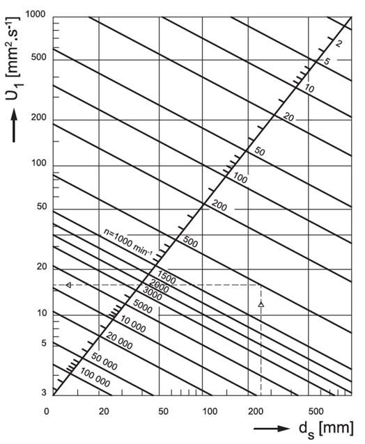
Fig. 5.4
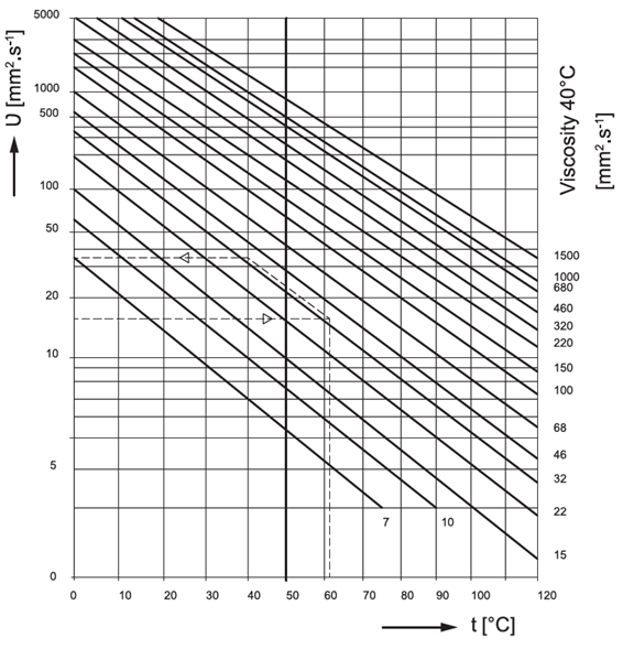
Fig. 5.5
5.7 ZKL-reported durability
The use of the L10 calculation of basic durability as bearing performance parameter criteria has demonstrated, over many years, to be satisfactory. This calculation is associated with 90% reliability in conjunction with the use of superior materials, a superior technological design, and under normal operating conditions.Notwithstanding, many applications require that the calculation be performed for a different reliability level or for more precise lubrication and contamination conditions. It was determined, with the use of advanced high quality bearing steel, that under favourable operating conditions and when contact stresses fall below the limit values and provided that the bearing steel fatigue stress limit is not exceeded, a higher durability than L10 can be achieved. Under unfavourable operating conditions, on the other hand, the bearing durability can in fact be shorter than L10 .
A system approach of fatigue-related durability was applied when creating the method of calculating ZKL modified durability. The impact on the durability of the system (bearing) is described in the following text and considers the influence of variance and the interaction of mutually related factors on the overall life. These factors are demonstrated through increased contact stress in the contact area, which leads to decreased service life.
These factors are used in the modified durability equation.
L_m=a_1⋅a_ZKL⋅L_10
a_1 - reliability coefficient for other than 90 % reliability, see table 5.6
a_ZKL - modified life coefficient
L_10 - basic durability [10^6 ot]
Provided that the lubrication conditions, cleanliness of the environment, and other operation conditions are favourable, an advanced, high-quality bearing can, under a certain load, achieve infinite service life. The fatigue load limit for bearings manufactured from generally high-quality bearing material and workmanship is such a load, that the contact pressure exerted on roller elements in the bearing is approximately 1500 MPa. This stress value takes into account the additional stresses caused by manufacturing tolerances and operating conditions. Decreased product precision and quality of materials leads to a lower fatigue load limit.
The contact stress in many applications is greater than 1500 MPa. Such operating conditions lead to reduced bearing life.
The operating influences can be related to the applied stress and rigidity of the material.
- Notches lead to the formation of edge stresses.
- A thin film of oil increases the stress at the contact area between the orbit and the roller element.
- Increased temperature decreases the fatigue load limit (its strength) of the material.
- A static inner ring (increased overlap) leads to increased orbital stress
A theoretical explanation of how to incorporate additional influences, such as the radial clearance during operation and the variable stress on orbits from tilting, is explained in ISO/TS 16281.
5.7.1 Fatigue load limit
5.7.2 Determining the modified durability coefficient
- The fatigue load and bearing load
- Lubrication (type of lubricant, viscosity, revolution speed, bearing size, additives)
- Environment (degree of contamination, packing)
- Contaminating particles (strength and size of particles in relation to bearing size, lubrication and filtration method)
- Installation (cleanliness during installation)
The a_ZKL Fatigue life coefficient is derived from the following equation:
a_ZKL=f((e_C⋅C_or)/P,κ)
Faktors e_C and κ adjust for contamination and lubrication conditions.
5.7.3 Contamination factor
Decreased bearing life caused by the effect of sold particles in the lubricant film depends on:
- The type, size, strength, and amount of particles
- The lubricating film thickness (relative viscosity κ)
- Bearing size
| Contamination level | eC | |
| Dpw < 100 mm | Dpw ≥ 100 mm | |
| Extremely clean | 1 | 1 |
| Particle size in the order of lubricating film thickness, Laboratory conditions | ||
| Highly clean | 0,8 to 0,6 | 0,9 to 0,8 |
| Oil filtered through a very fine filter, typical conditions for a bearing with plastic housing and lifetime lubricant filling | ||
| Normally clean | 0,6 to 0,5 | 0,8 to 0,6 |
| Oil filtered through a fine filter, typical conditions for a bearing with metal-sheet housing and lifetime lubricant filling | ||
| Mild contamination | 0,5 to 0,3 | 0,6 to 0,4 |
| Minor contamination in lubricant | ||
| Typical contamination | 0,3 to 0,1 | 0,4 to 0,2 |
| Typical bearing conditions without integrated bearing glands, particles causing wear enter bearing from vicinity | ||
| Strong contamination | 0,1 to 0 | 0,1 to 0 |
| The bearing environment is strongly contaminated, bearing housing with insufficient bearing glands | ||
| Very strong contamination | 0 | 0 |
Detailed calculation of the contamination factor
Table 5.7 lists the approximate contamination factor values. If the situation requires the use of more detailed calculations, the more precise calculation, provided below, must be used.A contamination factor may be established for the following types of lubricants:
- Circulating oil lubrication with on-line filtration
- Oil bath lubrication or circulating lubrication with off-line filtration
- Grease
β_x=n_1/n_2 , where
β_x filtration ratio for particles of determined size x
n_1 number of particles per unit of volume (100 ml) larger than x, prior to passage through filter
n_2 number of particles per unit of volume (100 ml) larger than x, after passage through filter
The filter ratio determined the filter efficiency.
Circulating lubrication with on-line filtration
The β_x filter ratio with particles of size x in µm according to standard ISO 16889 is the most influential factor when choosing the corresponding diagram.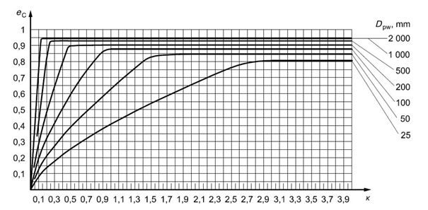
Fig. 5.7 Fouling factor for a circulating oil lubrication system with on-line filtration
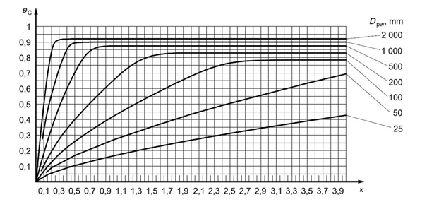
Fig.5.8 Fouling factor for a circulating oil lubrication system with on-line filtration
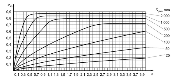
Fig. 5.9 Fouling factor for a circulating oil lubrication system with on-line filtration
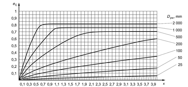 Fig. 5.10 Fouling factor for a circulating oil lubrication system with on-line filtration
Oil bath lubrication or circulating lubrication with off-line filtration
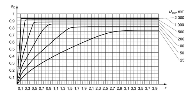
Fig. 5.11 Fouling factor for oil bath lubrication or for oil lubrication with offline filtration ISO 4406 – degree of contamination by solid particles -13/10
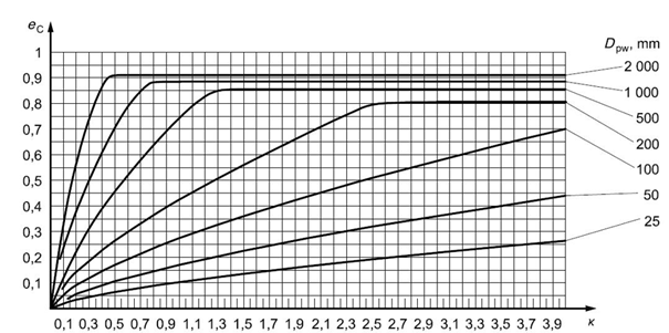
Fig. 5.12 Fouling factor for oil bath lubrication or for oil lubrication with offline filtration ISO 4406 – degree of contamination by solid particles -15/12
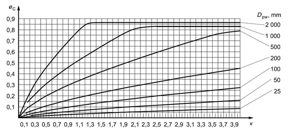
Fig. 5.13 Fouling factor for oil bath lubrication or for oil lubrication with offline filtration ISO 4406 – degree of contamination by solid particles -17/14
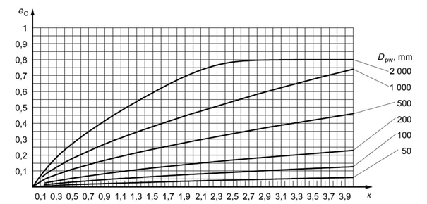
Fig. 5.14 Fouling factor for oil bath lubrication or for oil lubrication with offline filtration ISO 4406 – degree of contamination by solid particles -19/16
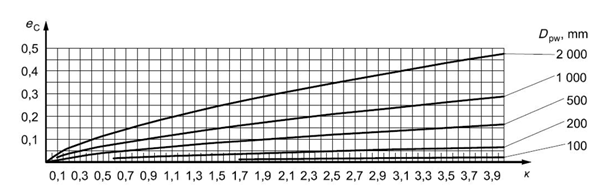 Fig. 5.15 Fouling factor for oil bath lubrication or for oil lubrication with offline filtration ISO 4406 – degree of contamination by solid particles -21/18
Grease
| Operating conditions | Contamination level |
| Very clean installation, very good packing relative to operating conditions, continuous lubrication or lubrication in short intervals (Bearings with integrated bearing glands) | Highly clean |
| Clean installation, good packing, additional lubrication per manufacturer specifications (Bearings with integrated bearing glands) | Normally clean |
| Clean installation, average sealing capacity relative to operating conditions | Mild contamination |
| On-site-installation, bearing and housing insufficiently washed following installation, poor sealing capacity relative to operating conditions, re-lubrication intervals longer than recommended | Strong contamination |
| Installation in a contaminated environment, insufficient gland packaging, long re-lubrication intervals | Very strong contamination |
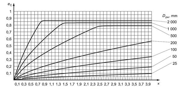
Fig. 5.16 Fouling factor for grease lubrication – moderate pollution
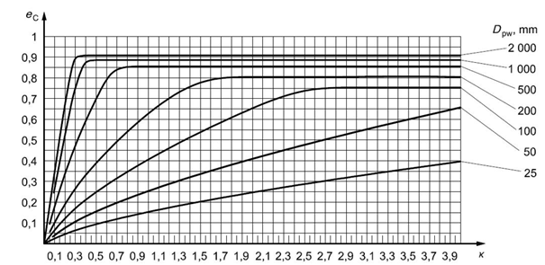
Fig. 5.17 Fouling factor for grease lubrication– usual purity
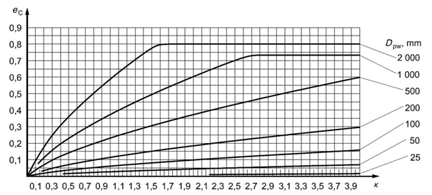
Fig. 5.18 Fouling factor for grease lubrication - strong contamination
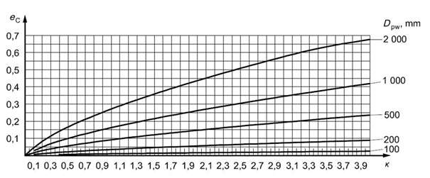
Fig. 5.19 Fouling factor for grease lubrication – very strong contamination
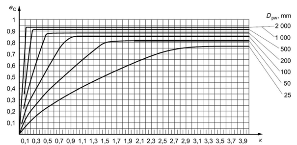
Fig. 5.20 Fouling factor for grease lubrication – high purity
5.7.4 Viscosity ratio
κ=ν/ν_1
In order to create sufficient lubricating film, the lubricant must maintain a certain minimal viscosity at operating temperature. The bearing life may be increased by increasing the operating viscosity ν.
The reference kinematic viscosity can be determined from figure 5.4 or by using the following equations:
ν_1=45000⋅n^(-0,83)⋅D_pw^(-0,5) for n< 1000 ot/min
ν_1=45000⋅n^(-0,5)⋅D_pw^(-0,5) for n≥ 1000 ot/min
Where D_pw=0,5⋅(d+D) is the bearing mean diameter
5.7.5 Calculating the modified durability coefficient
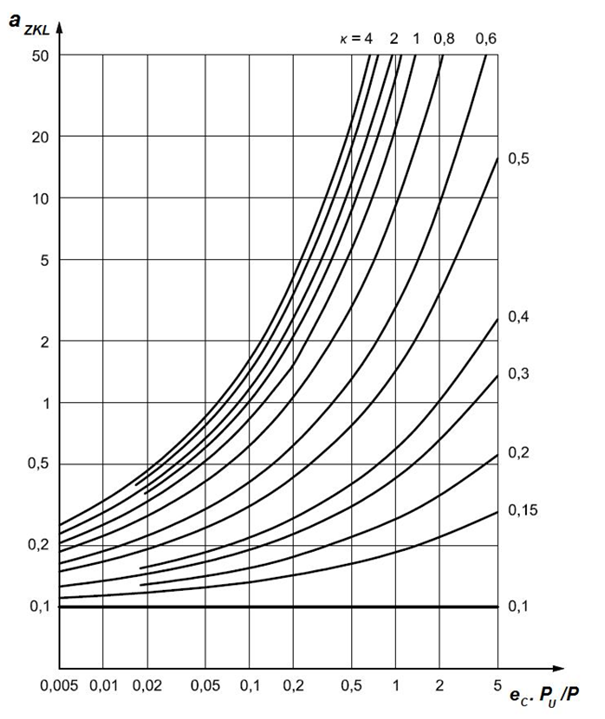
Fig. 5.21 Coefficient of life modification factor for thrust ball bearings
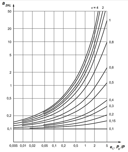
Fig. 5.22 Coefficient of life modification factor for thrust ball bearings
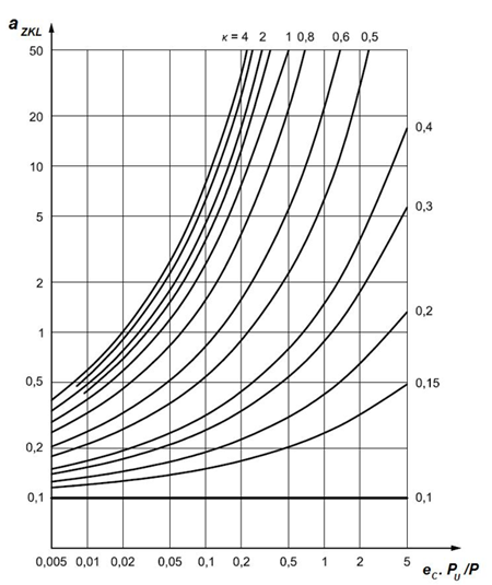
Fig. 5.23 Coefficient of life modification factor for deep groove ball bearings
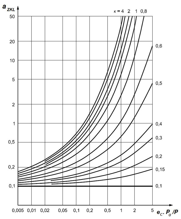
Fig. 5.24 Coefficient of life modification factor for spherical plain bearings
5.8 Equivalent dynamic load
The bearing in the structural node is exposed generally to acting forces of various magnitudes at various revolution speeds and with various periods of action. In terms of the calculation method, the applied forces must be recalculated at constant load, during which the bearing has the same durability as achieved under actual load. This recalculated constant radial or axial load is called equivalent load P, or Pr (radial) or Pa (axial), resp.5.8.1 Combined loads
Constant load method
The external forces applied on the bearing do not change in size or in relation to time.Radial bearings
If constant radial or axial forces simultaneously act on a radial bearing, the following equation for calculating the radial dynamic load applies:P_r=X⋅F_r+Y⋅F_a [kN]
P_r - radial equivalent dynamic load [kN]
F_r - radial force acting on the bearing [kN]
F_a - axial force acting on the bearing [kN]
X - radial load coefficient
Y - axial load coefficient
Coefficients X and Y are dependent on the ratio Fa / Fr. The values X and Y are provided in the table or in the commentary preceding each structural group, where further information is provided for bearing calculations of the respective structural group.
Axial bearings
Thrust ball bearings can only transfer forces acting axially and the following equation applied for calculating the axial equivalent dynamic load:P_a=F_a [kN]
P_a - axial equivalent dynamic load [kN]
F_a - axial bearing load [kN]
Spherical-roller thrust bearings can also transfer certain radial loads, however, only when a simultaneous axial load is applied, while observing the following condition:
P_a=F_a+1,2⋅F_r [kN]
Variable loading method
A real variable load, whose time course is known, is replaced by a mean intended load to enable calculation. This intended load has the same effect on the bearing as an actual variable load.5.8.2 Change in load magnitude at constant revolution speed
F_s=(∑_(i=1)^n▒〖〖F_i〗^3⋅q_i/100〗)^(1/3) [kN]
F_s - intended mean constant load [kN]
F_i=F_1,...,F_n - constant partial actual load [kN]
q_i=q_1,...,q_n - proportion of partially acting loads [%]
If a variable load acts on a bearing, while the rotation speed meanwhile changes (fig. 5.26), we calculate the mean intended load using the equation
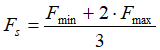 [kN]
[kN]
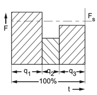 Fig. 5.25 |
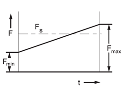 Fig. 5.26 |
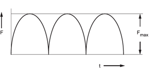 Fig. 5.27 |
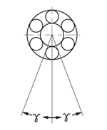 Fig. 5.28 |
Provided that the actual load has a sinusoid shape (fig. 5.27), the mean intended load is given by F_s=0,75⋅F_max [kN]
5.8.3 Change in load magnitude when rotation speed changes
F_s=((∑_(i=1)^n▒〖F_i^3⋅q_i⋅n_i 〗)/(∑_(i=1)^n▒〖q_i⋅n_i 〗))^(1/3) [kN]
n_i=n_1,...,n_n - constant rotation speed during action of partial loads F_1,...,F_n [〖min〗^(-1)]
q_i=q_1,...,q_n proportion of partially acting loads and frequencies [%]
If the rotation speed only changes in relation to time, the intended mean rotation speed is calculated using the equation
n_s=(∑_(i=1)^n▒g_i ⋅n_i)/100 [〖min〗^(-1)]
n_s - mean rotation speed [〖min〗^(-1)]
5.8.4 Oscillating motion of the bearing
F_s=F_r⋅(γ/90)^(1/p) [kN]
F_s - mean intended load [kN]
F_r - actual radial load [kN]
γ - amplitude of oscillation [°]
p - ball bearing exponent p=3
For roller, needle roller, spherical-roller, and tapered-roller bearings p=10/3
5.9 Effect of temperature
The supplied range of bearings is designated for use in environments with a temperature of up to 120°C. Larger spherical-roller bearings are manufactured, by default, for operation in temperatures up to 200°C. The exception are particular double-row spherical-roller bearings with polyamide races and single-row ball bearings equipped with glands (RS, 2RS, RSR, 2RSR), which may be used short-term in temperatures up to 150°C. More information about these bearings is available in chapter 12 “Manufacturer data”.Roller-contact bearings designed for higher operating temperatures are manufactured to ensure their required physical and mechanical properties and dimensional stability. Housing solutions at higher operating temperatures should be consulted with the supplier.
The and dynamic load capacity values Cr and Ca provided within the tables of the publication must, in the case of higher operating temperatures, be multiplied by the coefficient ft, as specified in table 5.9.
| ft Coefficient values | ||||
| operating temperature up to [ ° ] | 150 | 200 | 250 | 300 |
| ft coefficient | 0,95 | 0,9 | 0,75 | 0,6 |
5.10 Static Load Rating
The radial static load rating Cor and axial static load rating Coa for each bearing is specified in the table section of the publication. The values Cor and Coa were determined by calculation according to international standard ISO 76.The static load rating is the load that corresponds to the calculated contact stress in the roller element and bearing orbit contact zone, under the greatest load.
- 4600 MPa for double-row self-aligning ball bearings
- 4200 MPa for other ball bearings
- 4000 MPa For roller, needle roller, spherical-roller, and tapered-roller bearings
The static load rating Cor is used for calculations, if the bearings
- rotate at very low speeds (n < 10 min-1)
- perform very slow oscillating motions
- under load do not move for a particular, extended period.
The maximum load that can act on a bearing should be used when calculating the equivalent static load of a bearing.
5.10.1 Equivalent static load
P_or=X_o⋅F_r+Y_o⋅F_a [kN]
P_oa=Y_o⋅F_a [kN]
P_or - radial equivalent static load [kN]
P_oa - axial equivalent static load [kN]
F_r - radial load [kN]
F_a - axial load [kN]
X_o - radial load coefficient
Y_o - axial load coefficient
| s0 Coefficient | |||
| Bearing motion | Load bearing method, bearing operation requirements | s0 | |
| Ball bearings | Roller-contact, needle-roller, spherical-roller, and tapered-roller bearings | ||
| rotational | significant impact loads, high demands on quite operation |
2 | 4 |
| after static loading, bearing turns at lower loads | 1,5 | 3 | |
| normal demands for quiet operation | |||
| normal operating conditions and normal operating requirements | 1 | 1,5 | |
| quiet operation without vibration(s) | 0,5 | 1 | |
| Oscillating | small oscillating angle with large frequency with occasional uneven loads | 2 | 3,5 |
| large oscillating angle with small frequency with relatively constant periodical loads | 1,5 | 2,5 | |
| non-rotating (at rest) | considerable impact loads | 1,5 to 1 | 3 to 2 |
| normal and low loads, bearing operation unburdened by increased demands | 1 to 0,4 | 2 to 0,8 | |
| spherical-roller thrust bearings during all types of motion and loading | - | 4 | |
Coefficients X0 and Y0 are specified in the table section of the publication. Detailed information is also provided here for determining the equivalent static load of bearings of a particular structural group.
5.10.2 Bearing safety during static loading
In practice, the bearing safety under static load is determined from the ratio Cor/Por or Coa/Poa and compared with the data in table 5.10, where the smallest permissible coefficient values s0 are specified for various operating conditions.
s_0=C_or/P_or and/or C_oa/P_oa
s_0 - safety coefficient under static load [kN]
C_or - radial dynamic load capacity [kN]
C_oa - axial dynamic load capacity [kN]
P_or - radial equivalent static load or max. acting force Frmax (fig. 5.29) under significant impact load, resp. [kN]
P_oa - axial equivalent static load or max. acting force Frmax (fig. 5.29) under significant impact load, resp. [kN]
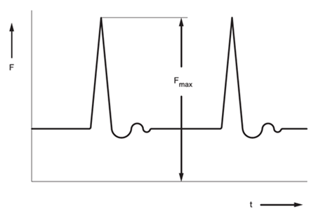
Fig. 5.29