4.1 Loads
4.1.1 Radial loads
Ball bearings are designed for small and medium-large loads. N- and NU-type ball bearings can only be burdened radially. Different type radial bearings can transfer both radial as well as axial loads.
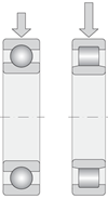
Fig. 4.1
4.1.2 Axial loads
Axial ball bearings and angular contact thrust ball bearings may, depending on the design, transfer axial loads in one or both directions (fig. 4.2a). In cases of extremely high axial loads, a thrust cylindrical roller or thrust roller bearings (fig. 4.2b). Other thrust bearings are only suitable for axial loads. Bilateral bearings are designed for bi-directional axial loads.
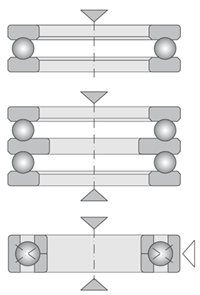 Fig. 4.2a |
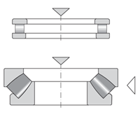 Fig. 4.2b |
4.1.3 Combined loads
Combined loads are composed of simultaneously acting radial and axial loads.
Axial load capacity of a bearing depends on the angle of contact. The larger the angle, the larger the axial load bearing capacity of the bearing. Larger axial clearance in single row ball bearings increases their load bearing capacity. Single and double-row angular contact ball bearings or tapered roller bearings are best for capturing combined loads (fig. 4.3a). Combined loads can also be borne by double-row spherical-roller bearings, thrust ball angular-contact bearings, and to a limited extent, also spherical-roller thrust bearings. Self-aligning ball bearings, NJ, NUP, or NJ roller-contact bearings and NU bearings with HJ attachment rings (fig. 4.3b) can be used for combined loads with a relatively small axial component.
 Fig. 4.3a |
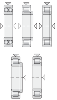 Fig. 4.3b |
Single-row angular-contact ball bearings, tapered roller bearings, NJ roller-contact bearings, and NU+HJ and axial spherical-roller bearings can only transfer unidirectional axial loads. If the arrangement of the active load changes, an additional bearing must be used. Combined single-row angular-contact ball bearings or single-row tapered roller bearings are provided for best capturing such combined loads (fig.
In addition to thrust bearings, ball bearings or four-point ball bearings can be used for capturing axial forces (fig. 4.4).
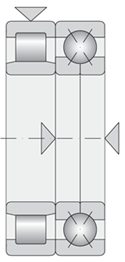
Fig. 4.4
4.1.4 Torque load
If the load application point lies outside of the bearing axis, then an overturning torque is created. The use of a radial double-row bearing or a double-row angular-contact ball bearing usually suffices for its transfer. The use of a par of single-row angular-contact ball bearings or tapered roller bearings installed back-to-back in pairs (into an “O”), however, are preferred (fig. 4.5).
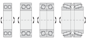
Fig. 4.5
4.2 Available space
In certain circumstances, it presents as a limiting condition for the bearing design. In small-diameter housing, the single-row ball bearing is most often applied (fig. 4.6). Roller-contact, spherical-roller, and taper-roller bearings may optionally be used for large diameter shafts (fig. 4.7). Various types of bearings also allow for a variety of types with various bearing section strengths. Where there is limited space in the radial or axial direction, bearings with a suitable cross-section are selected (fig. 4.8).
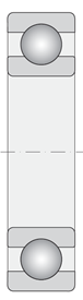 Fig. 4.6 |
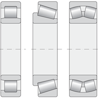 Fig. 4.7 |
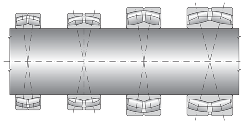
Fig. 4.8
4.3 Revolutions
Low-friction bearings should be used in housing subjected to high revolutions. Among such bearings are single-row ball bearings for purely radial loads. Angular-contact ball bearings in combined loads equally generate little heat. Both types of bearings are thus the most suitable for high revolution applications. Single-row roller-contact bearings are additionally suitable for high revolutions.From a design aspect, the rpms in thrust bearings are always lower than those of radial bearings.
4.4 Precision of operation
Bearings with normal diameter precision and operation (precision class P0) are sufficient for the most housing. In more demanding housing, e.g. for fitting machine tool spindles, bearings with higher precision must be used. Such bearings are designated by precision classes P6, P6E, P6X, P5, P5A, P4, P4A, P2, SP, UP. In the text, which is located at the beginning of individual tables, you are provided with more detailed information about precision classes, in which individual types are produced.4.5 Alignment
With regard to manufacturing inaccuracies and spindle deflections, mutual inclinations of bearing rings occur in the housing. This phenomenon should be expected and it is necessary to select bearings that compensate for the misalignment and installation inaccuracy. Self-aligning ball bearings (fig. 4.9a), two-row spherical-roller thrust bearings (fig. 4.9b), and spherical-roller thrust bearings (fig. 4.9c), are such types. The angle of inclination of such bearings depends on the type, size, and load. High rigidity bearings, such as roller-contact or ball bearings, can compensate for small misalignments, assuming that they are unburdened.
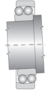 Fig. 4.9a |
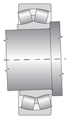 Fig. 4.9b |
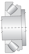 Fig. 4.9c |
4.6 Sliding axial movement
A fixed axial and free axial bearing is general used for supporting shafts, while the fixed axial bearing provides shaft guidance in both directions and the free axial bearing compensation for the axial change in length and thermal expansion. If axial displacement of thermally expanding components is prevented, then uncontrolled axial overloading of firmly fixed bearings may result.
Bearings that can carry combined loads are most suitable for capturing axial forces. Bearings that are best able to afford axial movement are NU and N roller-contact bearings (fig. 4.10). If ball or roller-contact bearings are used as free bearings, then one of the bearing rings (usually the outer) must be attached freely (fig. 4.11).
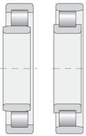 Fig. 4.10 |
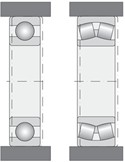 Fig. 4.11 |
Examples of axially guided and free axial bearing supports are illustrated in figures 4.12a to 4.12
- Axially guided ball bearing, free axial ball bearing
- Axially guided spherical-roller bearing, free axial spherical-roller bearing
- Axially guided ball bearing, free axial NU spherical-roller bearing
- Axially guided spherical-roller bearing, free axial NU roller-contact bearing
- Axially guided double-row angular-contact ball bearing, axially free NU roller-contact bearing
- Axially guided four-point contact ball bearing and an NU roller-contact bearing, free axial NU roller-contact bearing
- Axially guided double-row tapered-roller bearing, free axial NU roller-contact bearing
- Axially guided NUP roller-contact bearing, free axial NU roller-contact bearing
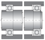 Fig. 4.12a |
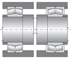 Fig. 4.12b |
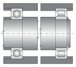 Fig. 4.12c |
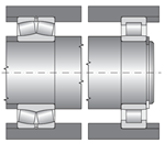 Fig. 4.12d |
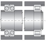 Fig. 4.12e |
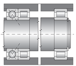 Fig. 4.12f |
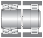 Fig. 4.12g |
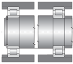 Fig. 4.12h |
4.7 Support rigidity
The support rigidity expresses the force required to achieve a defined deflection when using a flexible support. High rigidity is demanded, for example when supporting the main spindle in machine tools and pinion gear sets.The rigidity of line-contact bearings such as, e.g. roller-contact and tapered roller bearings is higher than in ball bearings due to the contact ratios between the rolling elements and orbits.
The bearings are pre-stressed to increase their rigidity.
4.8 Installation options
4.8.1 Bearings with a cylindrical bore
These bearings are more easily installed and removed, if they can be taken apart. This particularly applies for bearings within a fixed housing. Separable bearings are also suitable for use where frequent installation and removal are required. A ring with roller-contact elements may be installed separately, irrespective of the second ring (fig. 4.13a – 4.13c).
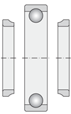 Fig. 4.13a |
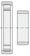 Fig. 4.13b |
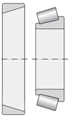 Fig. 4.13c |
4.8.2 Bearings with a tapered bore
Bearings with a tapered bore (fig. 4.14) are installed on a conical or cylindrical journal using a tapered sleeve or remove tapered-sleeve adapter. The radial clearance of bearings can be set during installation. Installation and removal of bearings is relatively simple.
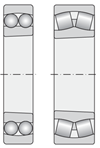
Fig. 4.14
4.9 Methods of packing bearings
ZKL Company provides a full range of unilaterally or bilaterally packed or encased roller-contact bearings. The bearings use contact (friction) packing (fig. 4.15) or are encased (fig. 4.16) using non-contact (touch-less) packing. Bearings with dual-side packaging are filled with plastic grease and do not require additional greasing during operation. The use of such bearings makes it possible to design economical and spatially undemanding housing. In other instances, care must be taken to monitor the structure of other components to prevent unwanted leaking of grease and entry of contaminants into the bearings.
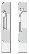 Fig. 4.15 |
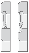 Fig. 4.16 |