8.1 Arrangement of bearings
To locate rotary shaft you need at least two bearings that are located in certain distance from each other. Depending on the application method, location with axially free and axially guiding bearing is selected; prestressed location or floating arrangement of bearings. See figure 4.12 in chapter Bearing type selection for examples of bearing arrangements.8.1.1 Location with axially free and axially guiding bearing
Axially guide bearing guides shaft in axial direction and besides radial forces captures also axial forces. Selection of bearing type to be used as axially guide bearing depends on the size of axial load and on requirements for accuracy of shaft location. Double row angular-contact ball bearing ensures more accurate axial guidance than e.g. ball or spherical-roller bearing. Accurate axial guidance can be achieved also by a pair of tapered bearings which are used as axially guide bearing. At lower axial load even NUP roller bearing can be used as axially guide bearing.
8.1.2 Symmetrical arrangement of bearings
8.1.3 Prestressed location
Location of prestressed bearing usually consists of symmetrically placed ball bearings with angular contact, or of tapered bearings. Prestress is achieved by use of springs. Such design compensates thermal dilatation. It is used in case when idle bearings can be exposed to vibrations. Prestressed bearings can reduce noise level, especially in small electric motors.
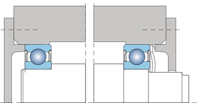
Fig. 8.1
Spring acts on outer race of one of the bearings whilst relevant outer race has to allow axial displacement in the body. Prestress remains practically constant even though the bearing axially moves due to thermal dilatation. Required prestress can be calculated using the below relation:
F = k . d
where
F Prestress force (kN)
k coefficient, see next
d bearing hole diameter in mm
Depending on design of electric motor, the coefficient may reach values of 0.005 up to 0.01.
If prestress is supposed to prevent bearing from getting damaged due to vibrations, it has to be set to higher level.
Then k = 0.02 has to be selected.
This method is however not suitable for locations that must feature high rigidity where the direction of acting load changes, or where shock load acts.
If certain optimum prestress value is exceeded, rigidity increases only insignificantly whilst friction and also service temperature in the bearing grow rapidly. This reduces durability of bearing since additional constant load acts on it. Informative relation between durability and prestress – clearance – is indicated in diagram in Fig. 8.2.
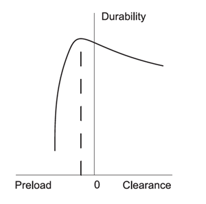
Fig. 8.2
8.2 Location design - General principles
Properties of bearings are fully utilised only when bearing races are supported along the entire circumference and width of orbits. Solid support surface can be of either cylindrical or tapered shape, in axial bearings the surface is flat. Support surfaces must be manufactured to have adequate accuracy, and must not be provided with grooves, holes, etc. Besides that, bearing races must be reliably secured to prevent them from turning in the body or on the shaft.Suitable radial security and adequate support can only be achieved if bearing races are mounted with overlap. If however easy assembly and disassembly are required, alternatively axial transferability of axially free bearing, fixed location of the race cannot be selected.
Where free location is chose, provisions must be adopted to avoid irrevocable wear during shifting the race.
Rotating shaft or another component located in roller bearings is guided by them in radial and axial direction so that the principal condition of definiteness of its movement is achieved. If possible, the component should certainly be located, i.e. supported radially on two spots and axially in one spot.
Examples of such location are shown in figures 4.12. Most common location is such where the shaft is located radially in two bearings one of which locks it in axial direction. Guide (fixed) bearing transfers radial load and also axial load in both directions. Radial bearings are mostly used as guide. They are able to transfer combined load, e.g. single row ball bearings, double row angular-contact bearings, double row ball tilting bearings, double row spherical-roller bearings or single row angular-contact ball bearings and tapered bearings. The lastly mentioned two bearing types must be assembled in pairs. Free bearing only transfers radial load and must allow certain displacement of the shaft in axial direction in order to prevent occurrence of undesired prestress caused by external effects (thermal dilatation, production inaccuracy of connecting location components, etc.).
Axial displacement can be achieved by shifting between one of the body rings and machine components directly associated with the bearing, e.g. between the outer bearing race and the hole in the body (Fig.4.12a, b), or directly in the bearing (Fig. 4.12 c to h).
Locations where higher radial force and axial load in higher revolution frequency act should be solved by the bearings capturing only radial or axial forces, see Fig. 8.3.
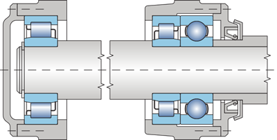
Fig. 8.3
In these cases, any of radial bearings can be used for radial guidance, and those radial bearings for axial guidance that feature the ability to transfer also axial load, alternatively a pair of these bearings or bidirectional axial bearings or a pair of unidirectional axial bearings. Condition is that axially guide bearings have to be located with radial clearance.
Another frequently used solution is location in two bearings the design of which allows capturing of both radial and axial load in both directions. Axial load is captured in turns by both bearings, always by the direction in which forces act and, at the same time, they transfer also radial load. An example of such location is shown in figure 8.4.
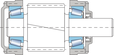
Fig. 8.4
In this case, a pair of single row tapered or single row angular-contact ball bearings is used as a well tested construction. Also other types of bearings that are able to transfer load in radial and axial direction at the same time can be used, e.g. single row bearings, alternatively single row roller bearings in NJ design, etc.
Radial and axial security of bearing on journal and in body hole or in another part has direct connection with the overall design location arrangement. When selecting the method of fixation, the character and intensity of acting forces has to be considered particularly, as well as service temperature at the point of location and the material of connecting components.
When specifying the dimensions of connecting parts, the designer needs to consider also the assembly and disassembly method and maintenance actions, besides the type and dimensions of the bearing.
8.2.1 Radial security of bearings
Proper radial fixation of bearing on journal and in body is very important for utilisation of its loading capacity and correct location function. In doing so, the following aspects need to be considered:
- safe fixation and uniform support of rings
- easy assembly and disassembly
- displacement of free bearing in axial direction
If proper radial fixation of bearing is selected, one needs to evaluate and consider the effect of the method of rotation and intensity of load.
Circumferential load
Circumferential load occurs when relevant bearing race turns, and the direction of load does not change, or when the race does not turn and the load rotates. The bearing race circumference is loaded successively in one revolution. In this case, loaded race must be always fixed with necessary overlap.Spot load
Spot load occurs when the bearing race stands and outer force is directed still in the same spot of the orbit, or when the race and force rotate at the same revolution frequency. The race to which the spot load acts can be located with clearance (mobile), if the conditions require so.Uncertain way of loading
In case of uncertain way of loading, the race is acted on by variable external forces the direction and change of load of which cannot be determined (e.g. unbalanced masses, shocks, etc.). Uncertain way of loading requires that both races are located with overlap (firmly). Under this condition in majority cases of location bearings with increased radial clearance have to be selected.Load intensity
The load directly affects selection of the size of overlap in location. The bigger the load of the bearing, the bigger overlap in location has to be selected. This particularly applies in cases of shock and vibration load of the bearing. Fixed location on journal or in hole of the body induces deformation of race, which reduces radial clearance. To ensure the needed radial clearance in cases of fixed location, sometimes bearings with increased radial clearance have to be used. Final clearance after assembly depends on the type and size of the bearing. Therefore the size of needed overlap of fitted race has to be considered by the type and size of the bearing. For bearings of smaller dimensions smaller overlaps are selected, and vice versa. Relatively smaller overlaps are used e.g. for ball bearings of the same bigness comparing to roller, tapered or spherical-roller bearings.Material and design of connecting pieces
Designing and determination of tolerances of connecting parts must take into account the materials used, as well as the construction of the connecting pieces. Results of practical experiences reflect in the below stated charts. When bearings are mounted in bodies made of light metal alloys or on journals of hollow shafts, location with higher overlaps has to be selected.Split bodies are not suitable for locations with big overlaps since they represent a risk of gripping the bearing in the dividing plane of the body.
Heating and warmth
Warmth generated in bearing may lead to release of overlap on the journal which may cause spinning the race. An opposite case may occur in the body. Heating causes clearance adjustment which will limit up to eliminate axial displacement of the race of free bearing in the body. Therefore we need to be very attentive to this factor when designing the location.Accuracy of bearing surfaces
Accuracy of bearing surfaces in terms of tolerances and geometrical shapes is important since it may transfer to orbits of bearing races. First of all, this has to be reflected in location designs which are highly focused on the running accuracy. Major share of inequality is transferred in thin profiles of bearing races.When normal accuracy level bearings are used, usually tolerances within the tolerance level IT6 are selected for the bearing surface on the journal, whilst for the bearing surface in the body the selected tolerance level is IT7.
For ball and roller bearings of smaller dimensions, IT5 level can be used for the journal and IT6 for the hole in the body.
For bearings of higher accuracy levels, for locations with high accuracy requirements, e.g. machine tool spindles, the recommended least level is IT5 for the shaft, and at least IT6 for the body.
Allowed deviation of circularity and cylindricality and allowed frontal runout of bearing and support surfaces for bearings must be smaller against the axis than the scope of tolerance of the diameters of the journal and the hole. With increasing accuracy of the bearings used, also the requirements for the accuracy of bearing surfaces grow. The recommended accuracy values of the bearing surfaces shape for bearings are stated in chart 8.1, and general tolerances IT2 to IT6 in chart 8.2
| Recommended accuracies of the shape of bearing surfaces for bearings | |||
| Accuracy level of bearing | Location place | Admissible deviation of cylindricality | Admissible frontal runout of support surfaces towards the axis |
| shaft | IT5/2 | IT3 | |
| P0, P6 | |||
| body | IT6/2 | IT4 | |
| shaft | IT3/2 | IT2 | |
| P5, P4 | |||
| body | IT4/2 | IT3 | |
| Basic tolerances IT2 to IT6 | ||||||
| Nominal diameter | Tolerance level | |||||
| over | to | IT2 | IT3 | IT4 | IT5 | IT6 |
| mm | µm | |||||
| 6 | 10 | 1,5 | 2,5 | 4 | 6 | 9 |
| 10 | 18 | 2 | 3 | 5 | 8 | 11 |
| 18 | 30 | 2,5 | 4 | 6 | 9 | 13 |
| 30 | 50 | 2,5 | 4 | 7 | 11 | 16 |
| 50 | 80 | 3 | 5 | 8 | 13 | 19 |
| 80 | 120 | 4 | 6 | 10 | 15 | 22 |
| 120 | 180 | 5 | 8 | 12 | 18 | 25 |
| 180 | 250 | 7 | 10 | 14 | 20 | 29 |
| 250 | 315 | 8 | 12 | 16 | 23 | 32 |
| 315 | 400 | 9 | 13 | 18 | 25 | 36 |
| 400 | 500 | 10 | 15 | 20 | 27 | 40 |
Assembly and disassembly of bearing
If any of the races is located with clearance (mobile), the assembly is easy. If the service conditions require that both races are located with overlap, a suitable type of bearing has to be chosen, e.g. separable bearing (tapered, cylindrical, needle), or a bearing with tapered hole. Shaft journals for location of sleeves for bearing with tapered hole can be within the h9 or h10 tolerance, geometrical shape must be within the accuracy IT5 or IT7, depending on the complexity of location.8.2.2 Axial displacement of free bearing races
At any service conditions the axial displacement of free bearing has to be ensured. If non-separable bearings are used, displacement of spot-loaded race will be reached by locating with clearance (mobile location). In bodies made of light metal alloys the hole has to be sleeved with a steel sleeve, if outer race is to be located with clearance. Reliable sliding ability in axial direction will be achieved if roller bearings of N and NU designs or radial needle bearings are used in the location.
The recommended tolerances of journal and hole diameters of connecting pieces are for radial and axial bearings stated in charts 8.3 to 8.10.
| Tolerances of journal diameters for radial bearings (applies for full steel shafts | |||||
| Journal diameter [mm] | |||||
| Service conditions | Examples of location | Ball bearings | Roller needle 1), tapered bearings | Spherical-roller bearings | Tolerance |
| Inner race spot load | |||||
| Small and normal load | Free wheel, pulleys | g6 2) | |||
| Pr ≦0,15 Cr | belt pulleys | All diameters | |||
| Big impact load | Wheels of conveyance trolleys, | h6 | |||
| Pr>0,15 Cr | napínací kladky | ||||
| Circumferential load of inner race or uncertain way of loading | |||||
| Small and variable load | Conveyers, | (18) to 100 | ≦40 | - | j6 |
| Pr ≦0,07 Cr | fans | (100) to 200 | (40) to 140 | - | k6 |
| Normal and big load | General engineering | ≦18 | - | - | j5 |
| Pr >0,07 Cr | (18) to 100 | ≦40 | - ≦40 | k5 (k6) 3) | |
| pumps, combustion engines | (100) to 140 | (40) to 100 | (40) to 65 | m5 (m6) 3) | |
| transmissions, | (140) to 200 | (100) to 140 | (65) to 100 | m6 | |
| woodworking machines | (140) to 200 | (100) to 140 | n6 | ||
| >200 | >140 | p6 | |||
| Extremely big load, shocks | Axle bearings of rail | - | (50) to 140 | (50) to 100 | n6 4) |
| heavy service conditions | vehicles, traction motors | - | (140) to 500 | (100) to 500 | p6 4) |
| Pr>0,15 Cr | rolling mills | - | >500 | >500 | r6 (p6) 4) |
| High location accuracy | Machine tools | ≦18 | - | - | h5 5) |
| at small load | (18) to 100 | ≦40 | - | j5 5) | |
| Pr ≦0,07 Cr | (100) to 200 | (40) to 140 | - | k5 5) | |
| (140) to 200 | - | m5 | |||
| Axial load exclusively | all diameters | j6 | |||
| Bearings with tapered hole and with clamp or dismantling sleeve | |||||
| All ways of loading | General locations | h9/IT5 | |||
| axle bearings | |||||
| of rail vehicles | all diameters | ||||
| Unexacting locations | h10/IT7 | ||||
- Does not apply to needle bearings without races
- For bearings tolerance f6 can be selected to ensure axial shift
- Tolerance in brackets is selected usually for single row tapered bearings or at low frequency revolutions where clearance diffusion does not have major significance.
- Bearings with increased radial clearance have to be used
- Tolerances for single row ball bearings of accuracy P5 and P4 are stated in chapter 12.2
| Tolerance of diameters of radial bearing body holes (applies to bodies of steel, alloy and cast steel) | ||||
| Service conditions | Sliding ability of outer race | Body | Examples of location | Tolerance |
| Circumferential load of outer race | ||||
| Big shock load | Does not slide | Single piece | Hubs | P7 |
| Pr>0,15 Cr | with roller bearings, | |||
| Thin-walled elements | crank pin bearings | |||
| Normal and big | Does not slide | Hubs with roller bearings | N7 | |
| load | travelling wheels of cranes, | |||
| Pr>0,07 Cr | crank shaft bearings | |||
| Small and variable | Does not slide | Converyer rollers, | M7 | |
| load Pr ≦0,07 Cr | tension pulleys | |||
| Uncertain way of loading | ||||
| Big shock load | Does not slide | Trakční motory | M7 | |
| Pr>0,15 Cr | ||||
| Big shock load | Usually does not | Single piece | Electromotors, pumps, | K7 |
| load Pr>0,07 Cr | slide | fans, crank shafts | ||
| Small and variable | Usually sliding | Electromotors, pumps, | J7 | |
| load Pr ≦0,07 Cr | fans, crank shafts | |||
| Accurate locations | ||||
| Small load | Usually does not | Roller bearings | K6 1) | |
| Pr ≦0,07 Cr | slide | for machine tools, | ||
| Sliding | Single piece | ball bearings for machine tools, | J6 2) | |
| Slightly pushing | malé elektromotory | H6 | ||
| Spot load of outer race | ||||
| Optional load | General engineering | H7 3) | ||
| axle bearings of rail vehicles | ||||
| Small and normal load | Slightly pushing | Single piece | General engineering | H8 |
| Pr ≦0,15 Cr | or two piece | less exacting mechanical eingineering | ||
| Paper machine drying cylinders | G7 4) | |||
| big electromotors | ||||
- For big load, stronger M6 or N6 tolerances are selected. For roller bearings with tapered hole, tolerances K5 or M5 are selected.
- Tolerances for single row ball bearings of accuracy P5 and P4 are stated in chapter 12.2
- For bearings with outer diameter D < 250 mm with thermal difference between outer race and body above 10 °C, tolerance G7 is selected
- For bearings with outer diameter D > 250 mm with thermal difference between outer race and body above 10 °C, tolerance F7 is selected.
| Tolerance of journal diameters for axial bearing | ||||
| Bearing type | Way of loading | Journal diameter [mm] | Tolerances | |
| Axial ball | j6 | |||
| Axial load exclusively | All diameters | |||
| Axial spherical-roller | j6 | |||
| Current axial and radial load | Spot load of shaft ring | All diameters | j6 | |
| Circumferential load of shaft ring or uncertain way of loading |
≦200 | k6 | ||
| (200) to 400 | m6 | |||
| > 400 | n6 | |||
| Tolerance of diameters of axial bearing body holes | ||||
| Bearing type | Way of loading | Note | Tolerances | |
| Axial ball | In common locations, the casing ring | H8 | ||
| Axial load exclusively | may feature clearance | |||
| Casing ring is | - | |||
| mounte with radial clearance | ||||
| Axial spherical-roller | Current axial | Spot load or | H7 | |
| and radial | uncertain way of loading | |||
| load | of casing ring | |||
| Circumferential load | M7 | |||
| Circumferential load | ||||
| Limit deviations of journal diameter tolerances | |||||||||||||||||
| Nominal diameter of journal | f6 | g5 | g6 | h5 | h6 | j5 | j6(js6) | k5 | |||||||||
| over | to | upper | lower | upper | lower | upper | lower | upper | lower | upper | lower | upper | lower | upper | lower | upper | lower |
| mm | µm | ||||||||||||||||
| 1 | 3 | -6 | -12 | -2 | -6 | -2 | -8 | 0 | -4 | 0 | -6 | 2 | -2 | 4 | -2 | 4 | 0 |
| 3 | 6 | -10 | -18 | -4 | -9 | -4 | -12 | 0 | -5 | 0 | -8 | 3 | -2 | 6 | -2 | 6 | 1 |
| 6 | 10 | -13 | -22 | -5 | -11 | -5 | -14 | 0 | -6 | 0 | -9 | 4 | -2 | 7 | -2 | 7 | 1 |
| 10 | 18 | -16 | -27 | -6 | -14 | -6 | -17 | 0 | -8 | 0 | -11 | 5 | -3 | 8 | -3 | 9 | 1 |
| 18 | 30 | -20 | -33 | -7 | -16 | -7 | -20 | 0 | -9 | 0 | -13 | 5 | -4 | 9 | -4 | 11 | 2 |
| 30 | 50 | -25 | -41 | -9 | -20 | -9 | -25 | 0 | -11 | 0 | -16 | 6 | -5 | 11 | -5 | 13 | 2 |
| 50 | 80 | -30 | -49 | -10 | -23 | -10 | -29 | 0 | -13 | 0 | -19 | 6 | -7 | 12 | -7 | 15 | 2 |
| 80 | 120 | -36 | -58 | -12 | -27 | -12 | -34 | 0 | -15 | 0 | -22 | 6 | -9 | 13 | -9 | 18 | 3 |
| 120 | 180 | -43 | -68 | -14 | -32 | -14 | -39 | 0 | -18 | 0 | -25 | 7 | -11 | 14 | -11 | 21 | 3 |
| 180 | 250 | -50 | -79 | -15 | -35 | -15 | -44 | 0 | -20 | 0 | -29 | 7 | -13 | 16 | -13 | 24 | 4 |
| 250 | 315 | -56 | -88 | -17 | -40 | -17 | -49 | 0 | -23 | 0 | -32 | 7 | -16 | 16 | -16 | 27 | 4 |
| 315 | 400 | -62 | -98 | -18 | -43 | -18 | -54 | 0 | -25 | 0 | -36 | 7 | -18 | 18 | -18 | 29 | 4 |
| 400 | 500 | -68 | -108 | -20 | -47 | -20 | -60 | 0 | -27 | 0 | -40 | 7 | -20 | 20 | -20 | 32 | 5 |
| 500 | 630 | -76 | -120 | - | - | -22 | -66 | - | - | 0 | -44 | - | - | 22 | -22 | - | - |
| 630 | 800 | -80 | -130 | - | - | -24 | -74 | - | - | 0 | -50 | - | - | 25 | -25 | - | - |
| 800 | 1000 | -86 | -142 | - | - | -26 | -82 | - | - | 0 | -56 | - | - | 28 | -28 | - | - |
| 1000 | 1250 | -98 | -164 | - | - | -28 | -94 | - | - | 0 | -66 | - | - | 33 | -33 | - | - |
| Nominal diameter of journal | k6 | m5 | m6 | n6 | p6 | h91) | IT5 | h101) | IT7 | ||||||||
| over | to | upper | lower | upper | lower | upper | lower | upper | lower | upper | lower | upper | lower | upper | lower | ||
| mm | µm | ||||||||||||||||
| 1 | 3 | 6 | 0 | 6 | 2 | 8 | 2 | 10 | 4 | 12 | 6 | 0 | -25 | 4 | 0 | -40 | 10 |
| 3 | 6 | 9 | 1 | 9 | 4 | 12 | 4 | 16 | 8 | 20 | 12 | 0 | -30 | 5 | 0 | -48 | 12 |
| 6 | 10 | 10 | 1 | 12 | 6 | 15 | 6 | 19 | 10 | 24 | 15 | 0 | -36 | 6 | 0 | -58 | 15 |
| 10 | 18 | 12 | 1 | 15 | 7 | 18 | 7 | 23 | 12 | 29 | 18 | 0 | -43 | 8 | 0 | -70 | 18 |
| 18 | 30 | 15 | 2 | 17 | 8 | 21 | 8 | 28 | 15 | 35 | 22 | 0 | -52 | 9 | 0 | -84 | 21 |
| 30 | 50 | 18 | 2 | 20 | 9 | 25 | 9 | 33 | 17 | 42 | 26 | 0 | -62 | 11 | 0 | -100 | 25 |
| 50 | 80 | 21 | 2 | 24 | 11 | 30 | 11 | 39 | 20 | 51 | 32 | 0 | -74 | 13 | 0 | -120 | 30 |
| 80 | 120 | 25 | 3 | 28 | 13 | 35 | 13 | 45 | 23 | 59 | 37 | 0 | -87 | 15 | 0 | -140 | 35 |
| 120 | 180 | 28 | 3 | 33 | 15 | 40 | 15 | 52 | 27 | 68 | 43 | 0 | -100 | 18 | 0 | -160 | 40 |
| 180 | 250 | 33 | 4 | 37 | 17 | 46 | 17 | 60 | 31 | 79 | 50 | 0 | -115 | 20 | 0 | -185 | 46 |
| 250 | 315 | 36 | 4 | 43 | 20 | 52 | 20 | 66 | 34 | 88 | 56 | 0 | -130 | 23 | 0 | -210 | 52 |
| 315 | 400 | 40 | 4 | 46 | 21 | 57 | 21 | 73 | 37 | 98 | 62 | 0 | -140 | 25 | 0 | -230 | 57 |
| 400 | 500 | 45 | 5 | 50 | 23 | 63 | 23 | 80 | 40 | 108 | 68 | 0 | -155 | 27 | 0 | -250 | 63 |
| 500 | 630 | 44 | 0 | - | - | 70 | 26 | 88 | 44 | 122 | 78 | 0 | -175 | 30 | 0 | -280 | 70 |
| 630 | 800 | 50 | 0 | - | - | 80 | 30 | 100 | 50 | 138 | 88 | 0 | -200 | 35 | 0 | -320 | 80 |
| 800 | 1000 | 56 | 0 | - | - | 90 | 34 | 112 | 56 | 156 | 100 | 0 | -230 | 40 | 0 | -360 | 90 |
| 1000 | 1250 | 66 | 0 | - | - | 106 | 40 | 132 | 66 | 186 | 120 | 0 | -260 | 46 | 0 | -420 | 105 |
- In journals manufactured within tolerances h9 and h10 for bearings with clamp or dismantling bushing, the circularity and cylindricality deviations must not exceed the basic tolerance IT5 and IT7.
| Limit deviations of hole diameter tolerances | |||||||||||||||
| Nominal diameter of hole | F7 | G6 | G7 | H6 | H7 | H8 | J6(Js6) | ||||||||
| over | to | upper | lower | upper | lower | upper | lower | upper | lower | upper | lower | upper | lower | upper | lower |
| mm | µm | ||||||||||||||
| 6 | 10 | 28 | 13 | 14 | 5 | 20 | 5 | 9 | 0 | 15 | 0 | 22 | 0 | 5 | -4 |
| 10 | 18 | 34 | 16 | 17 | 6 | 24 | 6 | 11 | 0 | 18 | 0 | 27 | 0 | 6 | -5 |
| 18 | 30 | 41 | 20 | 20 | 7 | 28 | 7 | 13 | 0 | 21 | 0 | 33 | 0 | 8 | -5 |
| 30 | 50 | 50 | 25 | 25 | 9 | 34 | 9 | 16 | 0 | 25 | 0 | 39 | 0 | 10 | -6 |
| 50 | 80 | 60 | 30 | 29 | 10 | 40 | 10 | 19 | 0 | 30 | 0 | 46 | 0 | 13 | -6 |
| 80 | 120 | 71 | 36 | 34 | 12 | 47 | 12 | 22 | 0 | 35 | 0 | 54 | 0 | 16 | -6 |
| 120 | 180 | 83 | 43 | 39 | 14 | 54 | 14 | 25 | 0 | 40 | 0 | 63 | 0 | 18 | -7 |
| 180 | 250 | 96 | 50 | 44 | 15 | 61 | 15 | 29 | 0 | 46 | 0 | 72 | 0 | 22 | -7 |
| 250 | 315 | 108 | 56 | 49 | 17 | 69 | 17 | 32 | 0 | 52 | 0 | 81 | 0 | 25 | -7 |
| 315 | 400 | 119 | 62 | 54 | 18 | 75 | 18 | 36 | 0 | 57 | 0 | 89 | 0 | 29 | -7 |
| 400 | 500 | 131 | 68 | 60 | 20 | 83 | 20 | 40 | 0 | 63 | 0 | 97 | 0 | 33 | -7 |
| 500 | 630 | 146 | 76 | 66 | 22 | 92 | 22 | 44 | 0 | 70 | 0 | 110 | 0 | 22 | -22 |
| 630 | 800 | 160 | 80 | 74 | 24 | 104 | 24 | 50 | 0 | 80 | 0 | 125 | 0 | 25 | -25 |
| 800 | 1000 | 176 | 86 | 82 | 26 | 116 | 26 | 56 | 0 | 90 | 0 | 140 | 0 | 28 | -28 |
| 1000 | 1250 | 203 | 98 | 94 | 28 | 133 | 28 | 66 | 0 | 105 | 0 | 165 | 0 | 33 | -33 |
| 1250 | 1600 | 235 | 110 | 108 | 30 | 155 | 30 | 78 | 0 | 125 | 0 | 195 | 0 | 39 | -39 |
| Nominal diameter of hole | J7(Js7) | K6 | K7 | M6 | M7 | N7 | P7 | ||||||||
| over | to | upper | lower | upper | lower | upper | lower | upper | lower | upper | lower | upper | lower | upper | lower |
| mm | µm | ||||||||||||||
| 6 | 10 | 8 | -7 | 2 | -7 | 5 | -10 | -3 | -12 | 0 | -15 | -4 | -19 | -9 | -24 |
| 10 | 18 | 10 | -8 | 2 | -9 | 6 | -12 | -4 | -15 | 0 | -18 | -5 | -23 | -11 | -29 |
| 18 | 30 | 12 | -9 | 2 | -11 | 6 | -15 | -4 | -17 | 0 | -21 | -7 | -28 | -14 | -35 |
| 30 | 50 | 14 | -11 | 3 | -13 | 7 | -18 | -4 | -20 | 0 | -25 | -8 | -33 | -17 | -42 |
| 50 | 80 | 18 | -12 | 4 | -15 | 9 | -21 | -5 | -24 | 0 | -30 | -9 | -39 | -21 | -51 |
| 80 | 120 | 22 | -13 | 4 | -18 | 10 | -25 | -6 | -28 | 0 | -35 | -10 | -45 | -24 | -59 |
| 120 | 180 | 25 | -14 | 4 | -21 | 12 | -28 | -8 | -33 | 0 | -40 | -12 | -52 | -28 | -68 |
| 180 | 250 | 30 | -16 | 5 | -24 | 13 | -33 | -8 | -37 | 0 | -46 | -14 | -60 | -33 | -79 |
| 250 | 315 | 36 | -16 | 5 | -27 | 16 | -36 | -9 | -41 | 0 | -52 | -14 | -66 | -36 | -88 |
| 315 | 400 | 39 | -18 | 7 | -29 | 17 | -40 | -10 | -46 | 0 | -57 | -16 | -73 | -41 | -98 |
| 400 | 500 | 43 | -20 | 8 | -32 | 18 | -45 | -10 | -50 | 0 | -63 | -17 | -80 | -45 | -108 |
| 500 | 630 | 35 | -35 | 0 | -44 | 0 | -70 | -26 | -70 | -26 | -96 | -44 | -114 | -78 | -148 |
| 630 | 800 | 40 | -40 | 0 | -50 | 0 | -80 | -30 | -80 | -30 | -110 | -50 | -130 | -88 | -168 |
| 800 | 1000 | 45 | -45 | 0 | -56 | 0 | -90 | -34 | -90 | -34 | -124 | -56 | -146 | -100 | -190 |
| 1000 | 1250 | 52 | -52 | 0 | -66 | 0 | -105 | -40 | -106 | -40 | -145 | -66 | -171 | -120 | -225 |
| 1250 | 1600 | 62 | -62 | 0 | -78 | 0 | -125 | -48 | -126 | -48 | -173 | -78 | -203 | -140 | -265 |
8.2.3 Axial security of bearings
Inner bearing race with cylindrical hole seated on journal with overlap (fixed location) is usually locked in axial direction using a circular clamp nut, terminal plate or snap ring whilst the other face is usually leaned by the shaft fitting. Adjacent components are used as support faces for inner races and, if needed, spacer rings are inserted between this component and the inner race of the bearing. Examples of axial fixation of bearing are shown in figure 8.5.
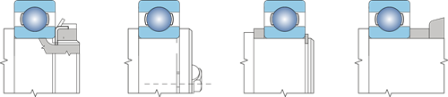
Fig. 8.5
Bearings with tapered hole mounted directly on tapered journal are usually secured with a safety nut screwed onto the thread on the shaft. If bearings are mounted on dismantling bush, the inner race must be supported, e.g. by a spacer ring. The spacer ring can form a part of labyrinth. The dismantling bush is axially fixed with terminal plate or safety nut.
Examples of axial fixation of bearing with tapered hole directly on tapered journal or by means of clamp or dismantling bush are shown in Fig. 8.6.
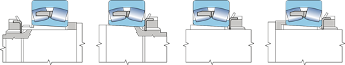
Fig. 8.6
Fa = 3B . d [N]
Fa – admissible axial load of bearing [N]
B – bearing width [mm]
d – bearing hole diameter [mm]
If axial displacement of outer race in body is not desirable, we can use a solution utilising the front support surface or seating surface of the bearing lid, nut or snap ring. Bearings with a groove for snap ring (NR) are less demanding in space, and their locking is simple.
Examples of solution are shown in Fig. 8.7.
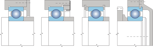
Fig. 8.7
8.3 Seal
Sealing the bearing space is very important since harmful substances present in the proximity of the bearing affect it and often even put it out of service. Seal has also an opposite function – it prevents the lubricant from leaking out of the bearing and from the stowage compartment. For that reason, the seal has always to be designed considering the service conditions of the machine or equipment, lubrication method, maintenance options and economic aspects of production and use.8.3.1 Contact-free sealing
This type of seal features only a tight gap between the non-rotary and rotary component which is sometimes filled with plastic lubricant. In this design no wear due to friction occurs, and therefore this seal suits to use for highest circumferential speeds and high service temperatures. Examples of slotted seals are shown in Fig. 8.8
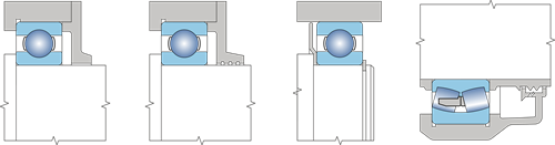
Fig. 8.8
Another very efficient seal is a labyrinth seal which can be used to enhance the packing effect by higher number of labyrinths or extension of sealing slots. See Fig.8.9. for examples of this seal.
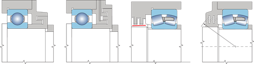
Fig. 8.9
8.3.2 Friction sealing
Friction sealing is made of elastic or soft but sufficiently solid and impermeable material that is inserted between the rotary and fixed component. Such seal is usually cheap and suits to various constructions. Disadvantage is sliding friction touching the surfaces which limits the use of it for high circumferential speeds.
The simplest is seal with a felt ring (Fig. 8.10). It suits to service temperatures within -40 °C and +80 °C and to circumferential even to 7 m.s-1, whilst the maximum required surface roughness of the sliding surface is Ra = 0.16, and minimum hardness 45 HRC or treatment by hard chromium plating. Dimensions of felt rings and grooves are solved by relevant national standards.
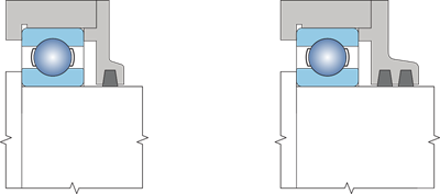
Fig. 8.10
A very frequent sealing method is sealing with shaft rings (Fig. 8.11). Shaft rings are made of rubber or other suitable plastics, stiffened by metal stiffener. According by the material used they suit to service temperatures from -30 °C to +160 °C. Admissible circumferential speed depends on the roughness of the sliding surface roughness:
- to 2 m.s-1 the roughness is max Ra= 0.8,
- to 4 m.s-1 the roughness is max Ra= 0.4,
- to 12 m.s-1 the roughness is max Ra= 0.2.
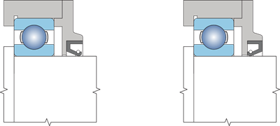
Fig. 8.11
Besides the stated most common sealing rings there are other friction seal designs that utilise specifically shaped sealing rings made of rubber, plastic, etc., or special elastic metal rings. This seal is either selected for locations with high demands on sealing the bearing space (bog contamination of ambient area, high temperature, effect of chemicals), or due to economic reasons in bulk and large lot production. Examples are shown in Fig. 8.12.
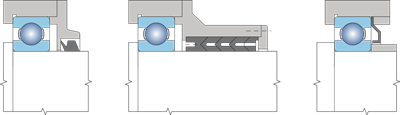
Fig. 8.12
8.3.3 Combined seals
Enhanced sealing effect is achieved by combination of contact-free and friction sealing. Such seals are recommended for humid and contaminated environment. Example is shown in Fig. 8.13.
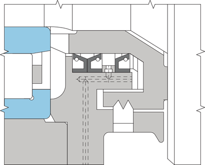
Fig. 8.13