7. Bearings - general data
Найти дистрибьютора
7.1 Bearing design data
Besides the suitable type of bearing and the size of it, additional design characteristics that define the bearing in location design have to be defined. The location designed is the one usually responsible for the bearing design. This person has to consider the requirements for accuracy of run, service temperature and lubrication, as well as the assembly and disassembly method. In order to meet all different requirements for proper run of bearing, bearings are produced in many versions that are characterized with an additional identification of bearings. Thus, bearings with required tolerances, clearances, materials, cage design or sealing can be selected. Also, accordingly with the identification system, bearings can be specified for certain service conditions that may be characteristic with high revolutions or high temperature, or alternatives of bearings for certain locations can be selected by the knowledge of identification of other bearing manufacturers.7.2 Main dimensions
Roller bearings are supplied as a final machine part, and the designer has at disposal fixed dimensions that ensure easy exchangeability. Standardisation applies to outer dimensions important in the assembly point of view. It is convenient for manufacturers and users of bearings for technological and thus also economic reasons. It however does not state inner dimensions, such as the quantity and dimensions of rolling bodies, or designs of cages. Despite that, due to the long-term development and various design and production technology optimisations even the inner design of bearings becomes united to a significant extent.The ISO international organization came up with dimension plans for roller bearings of metric dimensions that are defined in the below listed documents:
- ISO 15:1998 platí pro radiální valivá ložiska metrických rozměrů, s výjimkou kuželíkových ložisek
- ISO 355:1997 platí pro radiální kuželíková ložiska metrických rozměrů
- ISO 104:2002 platí pro axiální valivá ložiska metrických rozměrů
- ISO 582:1995 uvádí maximální hodnoty sražení montážních hran ložisek
7.2.1 ISO dimension plans
ISO dimension plan allocates to each bearing hole diameter d multiple outer diameters D, and to those different widths B – or – more precisely - T for radial and H for axial bearings. Bearings with the same hole diameter and same outer diameter belong in one diameter row identified by ascending outer diameter with figures 7, 8, 9, 0, 1, 2, 3, 4. Every diameter row contains bearings of different width rows by ascending width: 8, 0, 1, 2, 3, 4, 5, 6 and 7 for radial bearings. Width rows of radial bearings correspond with height rows of axial bearings (height rows by ascending height 7, 9, 1 and 2).
Combining the diameter and width row creates dimension rows that are identified by double figure where the first figure identified the width row, and the second figure identifies the diameter row. This system is clearly indicated in Fig. 7.1.
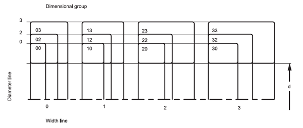
Fig. 7.1
The ISO dimension plan also contains dimensions of bearing ring edge fillet, the so-called installation fillet (Fig. 7.2). The chart section of the catalogue indicates minimum installation fillet values for individual bearing types that you need to know when designing radiuses of transmission of components forming the bearing location.
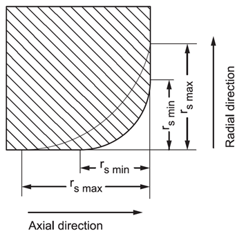
Obr. 7.2
See Chart 7.1 for an overview of the installation fillet complying with the international standard ISO 582.
| Limit dimensions of installation fillet | |||||||||
| Radial bearings except tapered | Tapered bearings | Axial bearings | |||||||
| rs min | d or D | rs min | d or D | rs min | rs min | ||||
| over | to | in radial direction | in axial direction | over | to | in radial direction | in axial direction | in radial and axial direction | |
| mm | |||||||||
| 0,15 | - | - | 0,3 | 0,6 | - | - | - | - | 0,3 |
| 0,2 | - | - | 0,5 | 0,8 | - | - | - | - | 0,5 |
| 0,3 | - | 40 | 0,6 | 1 | - | 40 | 0,7 | 1,4 | 0,8 |
| 40 | - | 0,8 | 1 | 40 | - | 0,9 | 1,6 | 0,8 | |
| 0,6 | - | 40 | 1 | 2 | - | 40 | 1,1 | 1,7 | 1,5 |
| 40 | - | 1,3 | 2 | 40 | - | 1,3 | 2 | 1,5 | |
| 1 | - | 50 | 1,5 | 3 | - | 50 | 1,6 | 2,5 | 2,2 |
| 50 | - | 1,9 | 3 | 50 | - | 1,9 | 3 | 2,2 | |
| 1,1 | - | 120 | 2 | 3,5 | - | - | - | - | 2,7 |
| 120 | - | 2,5 | 4 | - | - | - | - | 2,7 | |
| 1,5 | - | 120 | 2,3 | 4 | - | 120 | 2,3 | 3 | 3,5 |
| 120 | - | 3 | 5 | 120 | 250 | 2,8 | 3,5 | 3,5 | |
| - | - | - | - | 250 | - | 3,5 | 4 | 3,5 | |
| 2 | - | 80 | 3 | 4,5 | - | 120 | 2,8 | 4 | 4 |
| 80 | 220 | 3,5 | 5 | 120 | 250 | 3,5 | 4,5 | 4 | |
| 220 | - | 3,8 | 6 | 250 | - | 4 | 5 | 4 | |
| 2,1 | - | 280 | 4 | 6,5 | - | - | - | - | 4,5 |
| 280 | - | 4,5 | 7 | - | - | - | - | 4,5 | |
| 2,5 | - | 100 | 3,8 | 6 | - | 120 | 3,5 | 5 | - |
| 100 | 280 | 4,5 | 6 | 120 | 250 | 4 | 5,5 | - | |
| 280 | - | 5 | 7 | 250 | - | 4,5 | 6 | - | |
| 3 | - | 280 | 5 | 8 | - | 120 | 4 | 5,5 | 5,5 |
| 280 | - | 5,5 | 8 | 120 | 250 | 4,5 | 6,5 | 5,5 | |
| - | - | - | - | 250 | 400 | 5 | 7 | 5,5 | |
| - | - | - | - | 400 | - | 5,5 | 7,5 | 5,5 | |
| 4 | - | - | 6,5 | 9 | - | 120 | 5 | 7 | 6,5 |
| - | - | - | - | 120 | 250 | 5,5 | 7,5 | 6,5 | |
| - | -- | -- | - | 250 | 400 | 6 | 8 | 6,5 | |
| - | - | - | - | 400 | - | 6,5 | 8,5 | 6,5 | |
| 5 | - | - | 8 | 10 | - | 180 | 6,5 | 8 | 8 |
| - | - | - | - | 180 | - | 7,5 | 9 | 8 | |
| 6 | - | - | 10 | 13 | - | 180 | 7,5 | 10 | 10 |
| - | - | - | - | 180 | - | 9 | 11 | 10 | |
| 7,5 | - | - | 12,5 | 17 | - | - | - | - | 12,5 |
| 9,5 | - | - | 15 | 19 | - | - | - | - | 15 |
| 12 | - | - | 18 | 24 | - | - | - | - | 18 |
| 15 | - | - | 21 | 30 | - | - | - | - | 21 |
7.2.2 Accuracy of bearings
Majority locations can utilise roller bearings of normal accuracy level. Bearings with higher accuracy level are used in locations that require higher running accuracy, such as location of machine tool spindles, and where bearings exceed their limit revolutions.
The limit dimension and run accuracy values are stated in charts 7.2 to 7.12. These values comply with international standards ISO 492 a ISO 199. The P5A and P4A designation is used for bearings made in relevant accuracy level P5 and P4 but selected parameters feature higher accuracy level than is P5 and P4.
Symbols of quantities and their meaning
d –nominal hole diameter
d1 –nominal diameter of bigger theoretical tapered hole diameter
d2 –nominal diameter of shaft ring of bidirectional axial bearings
Δds – deviation of individual hole diameter from nominal dimension
Δdmp – deviation of mean diameter of cylindrical hole in individual radial plane (for tapered hole applies Δdmp for theoretical hole diameter)
Δd1mp – deviation of mean theoretical tapered hole diameter
Δd2mp – deviation of mean shaft ring hole diameter of bidirectional axial bearings in individual radial plane
Vdp – dispersion of individual hole diameter in individual radial plane
Vdmp – dispersion of mean cylindrical hole diameter
Vd2p – dispersion of shaft ring hole diameter of bidirectional axial bearings in individual radial plane
D – nominal external diameter
ΔDs –deviation of individual outer diameter from nominal dimension
ΔDmp – deviation of mean outer cylindrical surface diameter in individual radial plane
VDp – dispersion of individual outer cylindrical surface diameter in individual radial plane
VDmp –dispersion of mean outer cylindrical hole diameter
B – nominal inner ring width
T – nominal total width of tapered bearings
T1 – nominal effective width of inner semi-unit
T2 – nominal effective width of outer semi-unit
ΔBs – deviation of individual inner ring width
ΔCs – deviation of individual outer ring width
ΔTs – deviation of (total) individual bearing width
ΔT1s – deviation of effective width of inner semi-unit
ΔT2s – deviation of effective width of outer semi-unit
C – nominal outer ring width
VBs – dispersion of individual inner ring width
VCs – dispersion of individual outer ring width
Kia – radial runout of assembled bearing inner ring
Kea – radial runout of assembled bearing outer ring
Si – axial runout of shaft ring orbit
Se – axial runout of body ring orbit
Sia – axial runout of basic front of assembled bearing inner ring
Sea – axial runout of basic front of assembled bearing outer ring
Sd – axial runout of basic front
SD –runout of outer surface against ring front
Ss – runout of inner ring support front against basic front for single row tapered bearings
Limit values of individual parameters for different accuracy levels are stated in the below charts.
| Inner race | ||||||||||||||||
| d | Δdmp | Vdp | Vdmp | Kia | ΔBs | VBs | Δdmp | Δd1mp | -Δdmp | V1)dp | ||||||
| diameter rows | ||||||||||||||||
| 7,8,9 | 0,1 | 2,3,4 | ||||||||||||||
| over | to | max | min | max | max | max | max | max | max | min | max | max | min | max | min | max |
| 2,5 | 10 | 0 | -8 | 10 | 8 | 6 | 6 | 10 | 0 | -120 | 15 | - | - | - | - | - |
| 10 | 18 | 0 | -8 | 10 | 8 | 6 | 6 | 10 | 0 | -120 | 20 | - | - | - | - | - |
| 18 | 30 | 0 | -10 | 13 | 10 | 8 | 8 | 13 | 0 | -120 | 20 | 21 | 0 | 21 | 0 | 13 |
| 30 | 50 | 0 | -12 | 15 | 12 | 9 | 9 | 15 | 0 | -120 | 20 | 25 | 0 | 25 | 0 | 15 |
| 50 | 80 | 0 | -15 | 19 | 19 | 11 | 11 | 20 | 0 | -150 | 25 | 30 | 0 | 30 | 0 | 19 |
| 80 | 120 | 0 | -20 | 25 | 25 | 15 | 15 | 25 | 0 | 200 | 25 | 35 | 0 | 35 | 0 | 25 |
| 120 | 180 | 0 | -25 | 31 | 31 | 19 | 19 | 30 | 0 | -250 | 30 | 40 | 0 | 40 | 0 | 31 |
| 180 | 250 | 0 | -30 | 38 | 38 | 23 | 23 | 40 | 0 | -300 | 30 | 46 | 0 | 46 | 0 | 38 |
| 250 | 315 | 0 | -35 | 44 | 44 | 26 | 26 | 50 | 0 | -350 | 35 | 52 | 0 | 52 | 0 | 44 |
| 315 | 400 | 0 | -40 | 50 | 50 | 30 | 30 | 60 | 0 | -400 | 40 | 57 | 0 | 57 | 0 | 50 |
| 400 | 500 | 0 | -45 | 56 | 56 | 34 | 34 | 65 | 0 | -450 | 50 | 63 | 0 | 63 | 0 | 56 |
| 500 | 630 | 0 | -50 | 63 | 63 | 38 | 38 | 70 | 0 | -500 | 60 | - | - | - | - | - |
| 630 | 800 | 0 | -75 | - | - | - | - | 80 | 0 | -750 | 70 | - | - | - | - | - |
| 800 | 1000 | 0 | -100 | - | - | - | - | 90 | 0 | -1000 | 80 | - | - | - | - | - |
| 1000 | 1250 | 0 | -125 | - | - | - | - | 100 | 0 | -1250 | 100 | - | - | - | - | - |
| Outer race | ||||||||||
| D | ΔDmp | VDP | VDmp | Kea | ΔCs, ΔCs | |||||
| Diameter rows | ||||||||||
| 7,8,9 | 0,1 | 2,3,4 | bearings 2) | |||||||
| with covers | ||||||||||
| over | to | max | min | max | max | max | max | max | max | |
| mm | µm |
"Corresponds with
ΔBs, VBs of inner race of the same bearing" |
||||||||
| 6 | 18 | 0 | -8 | 10 | 8 | 6 | 10 | 6 | 15 | |
| 18 | 30 | 0 | -9 | 12 | 9 | 7 | 12 | 7 | 15 | |
| 30 | 50 | 0 | -11 | 14 | 11 | 8 | 16 | 8 | 20 | |
| 50 | 80 | 0 | -13 | 16 | 13 | 10 | 20 | 10 | 25 | |
| 80 | 120 | 0 | -15 | 19 | 19 | 11 | 26 | 11 | 35 | |
| 120 | 150 | 0 | -18 | 23 | 23 | 14 | 30 | 14 | 40 | |
| 150 | 180 | 0 | -25 | 31 | 31 | 19 | 38 | 19 | 45 | |
| 180 | 250 | 0 | -30 | 38 | 38 | 23 | - | 23 | 50 | |
| 250 | 315 | 0 | -35 | 44 | 44 | 26 | - | 26 | 60 | |
| 315 | 400 | 0 | -40 | 50 | 50 | 30 | - | 30 | 70 | |
| 400 | 500 | 0 | -45 | 56 | 56 | 34 | - | 34 | 80 | |
| 500 | 630 | 0 | -50 | 63 | 63 | 38 | - | 38 | 100 | |
| 630 | 800 | 0 | -75 | 94 | 94 | 55 | - | 55 | 120 | |
| 800 | 1000 | 0 | -100 | 125 | 125 | 75 | - | 75 | 140 | |
| 1000 | 1250 | 0 | -125 | - | - | - | - | - | 160 | |
| 1250 | 1600 | 0 | -160 | - | - | - | - | - | 190 | |
- Applies in optional radial hole plane
- Applies only to bearings of diameter rows 2, 3 and 4
| Accuracy of dimensions and run of radial bearings (except tapered) | |||||||||||
| Accuracy level P6 | |||||||||||
| Inner race | |||||||||||
| d | Δdmp | Vdp | Vdmp | Kia | ΔBs | VBs | |||||
| Diameter rows | |||||||||||
| 7,8,9 | 0,1 | 2,3,4, | |||||||||
| over | to | max | min | max | max | max | max | max | max | min | max |
| mm | µm | ||||||||||
| 2,5 | 10 | 0 | -7 | 9 | 7 | 5 | 5 | 6 | 0 | -120 | 15 |
| 10 | 18 | 0 | -7 | 9 | 7 | 5 | 5 | 7 | 0 | -120 | 20 |
| 18 | 30 | 0 | -8 | 10 | 8 | 6 | 6 | 8 | 0 | -120 | 20 |
| 30 | 50 | 0 | -10 | 13 | 10 | 8 | 8 | 10 | 0 | -120 | 20 |
| 50 | 80 | 0 | -12 | 15 | 15 | 9 | 9 | 10 | 0 | -150 | 25 |
| 80 | 120 | 0 | -15 | 19 | 19 | 11 | 11 | 13 | 0 | -200 | 25 |
| 120 | 180 | 0 | -18 | 23 | 23 | 14 | 14 | 18 | 0 | -250 | 30 |
| 180 | 250 | 0 | -22 | 28 | 28 | 17 | 17 | 20 | 0 | -300 | 30 |
| 250 | 315 | 0 | -25 | 31 | 31 | 19 | 19 | 25 | 0 | -350 | 35 |
| 315 | 400 | 0 | -30 | 38 | 38 | 23 | 23 | 30 | 0 | -400 | 40 |
| 400 | 500 | 0 | -35 | 44 | 44 | 26 | 26 | 35 | 0 | -450 | 45 |
| 500 | 630 | 0 | -40 | 50 | 50 | 30 | 30 | 40 | 0 | -500 | 50 |
| Outer race | ||||||||||
| D | ΔDmp | VDp | VDmp | Kea | ΔCs VCs | |||||
| Diameter rows | ||||||||||
| 7,8,9 | 0,1 | 2,3,4 | bearings 1) | |||||||
| with covers | ||||||||||
| over | to | max | min | max | max | max | max | max | max | |
| mm | µm | Corresponds with ΔBs, VBs of the inner race of the same bearing | ||||||||
| 6 | 18 | 0 | -7 | 9 | 7 | 5 | 9 | 5 | 8 | |
| 18 | 30 | 0 | -8 | 10 | 8 | 6 | 10 | 6 | 9 | |
| 30 | 50 | 0 | -9 | 11 | 9 | 7 | 13 | 7 | 10 | |
| 50 | 80 | 0 | -11 | 14 | 11 | 8 | 16 | 8 | 13 | |
| 80 | 120 | 0 | -13 | 16 | 16 | 10 | 20 | 10 | 18 | |
| 120 | 150 | 0 | -15 | 19 | 19 | 11 | 25 | 11 | 20 | |
| 150 | 180 | 0 | -18 | 23 | 23 | 14 | 30 | 14 | 23 | |
| 180 | 250 | 0 | -20 | 25 | 25 | 15 | - | 15 | 25 | |
| 250 | 315 | 0 | -25 | 31 | 31 | 19 | - | 19 | 30 | |
| 315 | 400 | 0 | -28 | 35 | 35 | 21 | - | 21 | 35 | |
| 400 | 500 | 0 | -33 | 41 | 41 | 25 | - | 25 | 40 | |
| 500 | 630 | 0 | -38 | 48 | 48 | 29 | - | 29 | 50 | |
| 630 | 800 | 0 | -45 | 56 | 56 | 34 | - | 34 | 60 | |
| 800 | 1000 | 0 | -50 | 75 | 75 | 45 | - | 45 | 75 | |
- Applies only to bearings of diameter rows 0, 1, 2, 3 and 4
| Accuracy of dimensions and run of radial bearings (except tapered) | ||||||||||||
| Accuracy level P5 | ||||||||||||
| Inner race | ||||||||||||
| d | Δdmp | Vdp | Vdmp | Kia | Sd | Sia1) | ΔBs | VBs | ||||
| Diameter rows | ||||||||||||
| 7,8,9 | 0,1,2,3,4 | |||||||||||
| over | to | max | min | max | max | max | max | max | max | max | min | max |
| mm | µm | |||||||||||
| 2,5 | 10 | 0 | -5 | 5 | 4 | 3 | 4 | 7 | 7 | 0 | -40 | 5 |
| 10 | 18 | 0 | -5 | 5 | 4 | 3 | 4 | 7 | 7 | 0 | -80 | 5 |
| 18 | 30 | 0 | -6 | 6 | 5 | 3 | 4 | 8 | 8 | 0 | -120 | 5 |
| 30 | 50 | 0 | -8 | 8 | 6 | 4 | 5 | 8 | 8 | 0 | -120 | 5 |
| 50 | 80 | 0 | -9 | 9 | 7 | 5 | 5 | 8 | 8 | 0 | -150 | 6 |
| 80 | 120 | 0 | -10 | 10 | 8 | 5 | 6 | 9 | 9 | 0 | -200 | 7 |
| 120 | 180 | 0 | -13 | 13 | 10 | 7 | 8 | 10 | 10 | 0 | -250 | 8 |
| 180 | 250 | 0 | -15 | 15 | 12 | 8 | 10 | 11 | 13 | 0 | -300 | 10 |
| 250 | 315 | 0 | -18 | 18 | 14 | 9 | 13 | 13 | 15 | 0 | -350 | 13 |
| 315 | 400 | 0 | -23 | 23 | 18 | 12 | 15 | 15 | 20 | 0 | -400 | 15 |
| Outer race | |||||||||||
| D | ΔDmp | Vdp | VDmp | Kea | SD | Sea1) | ΔCs | VCs | |||
| Diameter rows | |||||||||||
| 7,8,9 | 0,1,2,3,4 | ||||||||||
| over | to | max | min | max | max | max | max | max | max | max | |
| mm | µm | ||||||||||
| 6 | 18 | 0 | -5 | 5 | 4 | 3 | 5 | 8 | 8 | Corresponds with ΔBc of the inner race of the same bearing | 5 |
| 18 | 30 | 0 | -6 | 6 | 5 | 3 | 6 | 8 | 8 | 5 | |
| 30 | 50 | 0 | -7 | 7 | 5 | 4 | 7 | 8 | 8 | 5 | |
| 50 | 80 | 0 | -9 | 9 | 8 | 5 | 8 | 8 | 10 | 6 | |
| 80 | 120 | 0 | -10 | 10 | 8 | 5 | 10 | 9 | 11 | 8 | |
| 120 | 150 | 0 | -11 | 11 | 8 | 6 | 11 | 10 | 13 | 8 | |
| 150 | 180 | 0 | -13 | 13 | 10 | 7 | 13 | 10 | 14 | 8 | |
| 180 | 250 | 0 | -15 | 15 | 11 | 8 | 15 | 11 | 15 | 10 | |
| 250 | 315 | 0 | -18 | 18 | 14 | 9 | 18 | 13 | 18 | 11 | |
| 315 | 400 | 0 | -20 | 20 | 15 | 10 | 20 | 13 | 20 | 13 | |
| 400 | 500 | 0 | -23 | 23 | 17 | 12 | 23 | 15 | 23 | 15 | |
| 500 | 630 | 0 | -28 | 28 | 21 | 14 | 25 | 18 | 25 | 18 | |
| 630 | 800 | 0 | -35 | 35 | 26 | 18 | 30 | 20 | 30 | 20 | |
- Applies to ball bearings only
- Does not apply to covered bearings
| Accuracy of dimensions and run of radial bearings (except tapered) | ||||||||||||||
| Accuracy level P4 | ||||||||||||||
| Inner race | ||||||||||||||
| d | Δdmp | Δds1) | Vdp | Vdmp | Kia | Sd | Sia2) | ΔBs | VBs | |||||
| Diameter rows | ||||||||||||||
| 7,8,9 | 0,1,2,3,4 | |||||||||||||
| over | to | max | min | max | min | max | max | max | max | max | max | max | min | max |
| mm | µm | |||||||||||||
| 2,5 | 10 | 0 | -4 | 0 | -4 | 4 | 3 | 2 | 2,5 | 3 | 3 | 0 | -40 | 2,5 |
| 10 | 18 | 0 | -4 | 0 | -4 | 4 | 3 | 2 | 2,5 | 3 | 3 | 0 | -80 | 2,5 |
| 18 | 30 | 0 | -5 | 0 | -5 | 5 | 4 | 2,5 | 3 | 4 | 4 | 0 | -120 | 2,5 |
| 30 | 50 | 0 | -6 | 0 | -6 | 6 | 5 | 3 | 4 | 4 | 4 | 0 | -120 | 3 |
| 50 | 80 | 0 | -7 | 0 | -7 | 7 | 5 | 3,5 | 4 | 5 | 5 | 0 | -150 | 4 |
| 80 | 120 | 0 | -8 | 0 | -8 | 8 | 6 | 4 | 5 | 5 | 5 | 0 | -200 | 4 |
| 120 | 180 | 0 | -10 | 0 | -10 | 10 | 8 | 5 | 6 | 6 | 7 | 0 | -250 | 5 |
| 180 | 250 | 0 | -12 | 0 | -12 | 12 | 9 | 6 | 8 | 7 | 8 | 0 | -300 | 6 |
| Outer race | |||||||||||||
| D | ΔDmp | VDs1) | VDp | VDmp | Kea | SD | Sea2) | ΔCs | VCs | ||||
| Diameter rows3) | |||||||||||||
| 7,8,9 | 0,1,2,3,4 | ||||||||||||
| over | to | max | min | max | min | max | max | max | max | max | max | max | |
| mm | µm | ||||||||||||
|
"Corresponds with
ΔBs of the inner race of the same bearing" |
|||||||||||||
| 6 | 18 | 0 | -4 | 0 | -4 | 4 | 3 | 2 | 3 | 4 | 5 | 2,5 | |
| 18 | 30 | 0 | -5 | 0 | -5 | 5 | 4 | 2,5 | 4 | 4 | 5 | 2,5 | |
| 30 | 50 | 0 | -6 | 0 | -6 | 6 | 5 | 3 | 5 | 4 | 5 | 2,5 | |
| 50 | 80 | 0 | -7 | 0 | -7 | 7 | 5 | 3,5 | 5 | 4 | 5 | 3 | |
| 80 | 120 | 0 | -8 | 0 | -8 | 8 | 6 | 4 | 6 | 5 | 6 | 4 | |
| 120 | 150 | 0 | -9 | 0 | -9 | 9 | 7 | 5 | 7 | 5 | 7 | 5 | |
| 150 | 180 | 0 | -10 | 0 | -10 | 10 | 8 | 5 | 8 | 5 | 8 | 5 | |
| 180 | 250 | 0 | -11 | 0 | -11 | 11 | 8 | 6 | 10 | 7 | 10 | 7 | |
| 250 | 315 | 0 | -13 | 0 | -13 | 13 | 10 | 7 | 11 | 8 | 10 | 7 | |
| 315 | 400 | 0 | -15 | 0 | -15 | 15 | 11 | 8 | 13 | 10 | 13 | 8 | |
- Applies only to bearings of diameter rows 0, 1, 2, 3 and 4
- Applies to ball bearings only
- Does not apply to covered bearings
| Accuracy of dimensions and run of roller bearings with tapered hole | |||||||||||
| Accuracy level SP | |||||||||||
| Inner race | |||||||||||
| d | Δdmp | Δd1mp | -Δdmp | Vdp | Kia | Sd | ΔBs | VBs | |||
| over | to | max | min | max | min | max | max | max | max | min | max |
| mm | µm | ||||||||||
| 18 | 30 | 10 | 0 | 4 | 0 | 3 | 3 | 8 | 0 | -100 | 5 |
| 30 | 50 | 12 | 0 | 4 | 0 | 4 | 4 | 8 | 0 | -120 | 5 |
| 50 | 80 | 15 | 0 | 5 | 0 | 5 | 4 | 8 | 0 | -150 | 6 |
| 80 | 120 | 20 | 0 | 6 | 0 | 5 | 5 | 9 | 0 | -200 | 7 |
| 120 | 180 | 25 | 0 | 8 | 0 | 7 | 6 | 10 | 0 | -250 | 8 |
| 180 | 250 | 30 | 0 | 10 | 0 | 8 | 8 | 11 | 0 | -300 | 10 |
| 250 | 315 | 35 | 0 | 12 | 0 | 9 | 10 | 13 | 0 | -350 | 13 |
| 315 | 400 | 40 | 0 | 13 | 0 | 12 | 12 | 15 | 0 | -400 | 15 |
| 400 | 500 | 45 | 0 | 15 | 0 | 14 | 12 | 18 | 0 | -450 | 25 |
| Outer race | |||||||
| D | ΔDmp | VDp | Kea | SD | ΔCs, VCs | ||
| over | to | max | min | max | max | max | |
| mm | µm | ||||||
| 50 | 80 | 0 | -9 | 5 | 5 | 8 |
"Corresponds with
ΔBs and VBs of inner race of the same bearing" |
| 80 | 120 | 0 | -10 | 5 | 6 | 9 | |
| 120 | 150 | 0 | -11 | 6 | 7 | 10 | |
| 150 | 180 | 0 | -13 | 7 | 8 | 10 | |
| 180 | 250 | 0 | -15 | 8 | 10 | 11 | |
| 250 | 315 | 0 | -18 | 9 | 11 | 13 | |
| 315 | 400 | 0 | -20 | 10 | 13 | 13 | |
| 400 | 500 | 0 | -23 | 12 | 15 | 15 | |
| 500 | 630 | 0 | -28 | 14 | 17 | 18 | |
| 630 | 800 | 0 | -35 | 18 | 20 | 20 | |
| Accuracy of dimensions and run of roller bearings with tapered hole | |||||||||||
| Accuracy level UP | |||||||||||
| Inner race | |||||||||||
| d | Δdmp | Δd1mp | -Δdmp | Vdp | Kia | Sd | ΔBs | VBs | |||
| over | to | max | min | max | min | max | max | max | max | min | max |
| mm | µm | ||||||||||
| 18 | 30 | 6 | 0 | 2 | 0 | 3 | 1,5 | 3 | 0 | -25 | 1,5 |
| 30 | 50 | 7 | 0 | 3 | 0 | 3 | 2 | 3 | 0 | -30 | 2 |
| 50 | 80 | 8 | 0 | 3 | 0 | 4 | 2 | 4 | 0 | -40 | 3 |
| 80 | 120 | 10 | 0 | 4 | 0 | 4 | 3 | 4 | 0 | -50 | 3 |
| 120 | 180 | 12 | 0 | 5 | 0 | 5 | 3 | 5 | 0 | -60 | 4 |
| 180 | 250 | 14 | 0 | 6 | 0 | 6 | 4 | 6 | 0 | -75 | 5 |
| 250 | 315 | 17 | 0 | 8 | 0 | 8 | 5 | 6 | 0 | -90 | 6 |
| Outer race | |||||||
| D | ΔDmp | VDp | Kea | SD | ΔCs, VCs | ||
| over | to | max | min | max | max | max | |
| mm | µm | ||||||
| 50 | 80 | 0 | -6 | 3 | 3 | 2 |
"Corresponds with
ΔBs and VBs of inner race of the same bearing" |
| 80 | 120 | 0 | -7 | 4 | 3 | 3 | |
| 120 | 150 | 0 | -8 | 4 | 4 | 3 | |
| 150 | 180 | 0 | -9 | 5 | 4 | 3 | |
| 180 | 250 | 0 | -10 | 5 | 5 | 4 | |
| 250 | 315 | 0 | -12 | 6 | 6 | 4 | |
| 315 | 400 | 0 | -14 | 7 | 7 | 5 | |
| Accuracy of dimensions and run of tapered bearings | ||||||||||||||
| Accuracy level P0 | ||||||||||||||
| Inner race and total bearing width | ||||||||||||||
| d | Δdmp | Vdp | Vdmp | Kia | ΔBs | ΔTs | ΔT1s | ΔT2s | ||||||
| over | to | max | min | max | max | max | max | min | max | min | max | min | max | min |
| mm | µm | |||||||||||||
| 10 | 18 | 0 | -12 | 12 | 9 | 15 | 0 | -120 | 200 | 0 | 100 | 0 | 100 | 0 |
| 18 | 30 | 0 | -12 | 12 | 9 | 18 | 0 | -120 | 200 | 0 | 100 | 0 | 100 | 0 |
| 30 | 50 | 0 | -12 | 12 | 9 | 20 | 0 | -120 | 200 | 0 | 100 | 0 | 100 | 0 |
| 50 | 80 | 0 | -15 | 15 | 11 | 25 | 0 | -150 | 200 | 0 | 100 | 0 | 100 | 0 |
| 80 | 120 | 0 | -20 | 20 | 15 | 30 | 0 | -200 | 200 | -200 | 100 | -100 | 100 | -100 |
| 120 | 180 | 0 | -25 | 25 | 19 | 35 | 0 | -250 | 350 | -250 | 150 | -150 | 200 | -100 |
| 180 | 250 | 0 | -30 | 30 | 23 | 50 | 0 | -300 | 350 | -250 | 150 | -150 | 200 | -100 |
| Outer race | ||||||||
| D | ΔDmp | VDp | VDmp | Kea | ΔCs | |||
| over | to | max | min | max | max | max | max | min |
| mm | µm | |||||||
| 18 | 30 | 0 | -12 | 12 | 9 | 18 | 0 | -120 |
| 30 | 50 | 0 | -14 | 14 | 11 | 20 | 0 | -120 |
| 50 | 80 | 0 | -16 | 16 | 12 | 25 | 0 | -150 |
| 80 | 120 | 0 | -18 | 18 | 14 | 35 | 0 | -200 |
| 120 | 150 | 0 | -20 | 20 | 15 | 40 | 0 | -250 |
| 150 | 180 | 0 | -25 | 25 | 19 | 45 | 0 | -250 |
| 180 | 250 | 0 | -30 | 30 | 23 | 50 | 0 | -300 |
| 250 | 315 | 0 | -35 | 35 | 26 | 60 | 0 | -350 |
| 315 | 400 | 0 | -40 | 40 | 30 | 70 | 0 | -400 |
| Accuracy of dimensions and run of tapered bearings | ||||||||||||||
| Accuracy level P6X | ||||||||||||||
| Inner race and total bearing width | ||||||||||||||
| d | Δdmp | Vdp | Vdmp | Kia | ΔBs | ΔTs | ΔT1s | ΔT2s | ||||||
| over | to | max | min | max | max | max | max | min | max | min | max | min | max | min |
| mm | µm | |||||||||||||
| 10 | 18 | 0 | -12 | 12 | 9 | 15 | 0 | -50 | 100 | 0 | 50 | 0 | 50 | 0 |
| 18 | 30 | 0 | -12 | 12 | 9 | 18 | 0 | -50 | 100 | 0 | 50 | 0 | 50 | 0 |
| 30 | 50 | 0 | -12 | 12 | 9 | 20 | 0 | -50 | 100 | 0 | 50 | 0 | 50 | 0 |
| 50 | 80 | 0 | -15 | 15 | 11 | 25 | 0 | -50 | 100 | 0 | 50 | 0 | 50 | 0 |
| 80 | 120 | 0 | -20 | 20 | 15 | 30 | 0 | -50 | 100 | 0 | 50 | 0 | 50 | 0 |
| 120 | 180 | 0 | -25 | 25 | 19 | 35 | 0 | -50 | 150 | 0 | 50 | 0 | 100 | 0 |
| Outer race | ||||||||
| D | ΔDmp | VDp | VDmp | Kea | ΔCs | |||
| over | to | max | min | max | max | max | max | min |
| mm | µm | |||||||
| 18 | 30 | 0 | -12 | 12 | 9 | 18 | 0 | -100 |
| 30 | 50 | 0 | -14 | 14 | 11 | 20 | 0 | -100 |
| 50 | 80 | 0 | -16 | 16 | 12 | 25 | 0 | -100 |
| 80 | 120 | 0 | -18 | 18 | 14 | 35 | 0 | -100 |
| 120 | 150 | 0 | -20 | 20 | 15 | 40 | 0 | -100 |
| 150 | 180 | 0 | -25 | 25 | 19 | 45 | 0 | -100 |
| 180 | 250 | 0 | -30 | 30 | 23 | 50 | 0 | -100 |
| 250 | 315 | 0 | -35 | 35 | 26 | 60 | 0 | -100 |
| Accuracy of dimensions and run of tapered bearings | ||||||||
| Accuracy level P6 | ||||||||
| Inner race and total bearing width | ||||||||
| d | Δdmp | Kia | ΔBs | ΔTs | ||||
| over | to | max | min | max | max | min | max | min |
| mm | µm | |||||||
| 10 | 18 | 0 | -7 | 7 | 0 | -200 | 200 | 0 |
| 18 | 30 | 0 | -8 | 8 | 0 | -200 | 200 | 0 |
| 30 | 50 | 0 | -10 | 10 | 0 | -240 | 200 | 0 |
| 50 | 80 | 0 | -12 | 10 | 0 | -300 | 200 | 0 |
| 80 | 120 | 0 | -15 | 13 | 0 | -400 | 200 | -200 |
| 120 | 180 | 0 | -18 | 18 | 0 | -500 | 350 | -250 |
| Outer race | |||||
| D | ΔDmp | Kea | ΔCs | ||
| over | to | max | min | max | |
| mm | µm | ||||
| 18 | 30 | 0 | -8 | 9 |
"Corresponds with ΔBs
of inner race of the same bearing" |
| 30 | 50 | 0 | -9 | 10 | |
| 50 | 80 | 0 | -11 | 13 | |
| 80 | 120 | 0 | -13 | 18 | |
| 120 | 150 | 0 | -15 | 20 | |
| 150 | 180 | 0 | -18 | 23 | |
| 180 | 250 | 0 | -20 | 25 | |
| 250 | 315 | 0 | -25 | 30 | |
| Accuracy of dimensions and run of tapered bearings | |||||||||||
| Accuracy level P5 | |||||||||||
| Inner race and total bearing width | |||||||||||
| d | Δdmp | Vdp | Vdmp | Kia | Sd | ΔBs | ΔTs | ||||
| over | to | max | min | max | max | max | max | max | min | max | min |
| mm | µm | ||||||||||
| 10 | 18 | 0 | -7 | 5 | 5 | 5 | 7 | 0 | -200 | 200 | -200 |
| 18 | 30 | 0 | -8 | 6 | 5 | 5 | 8 | 0 | -200 | 200 | -200 |
| 30 | 50 | 0 | -10 | 8 | 5 | 5 | 8 | 0 | -240 | 200 | -200 |
| 50 | 80 | 0 | -12 | 9 | 6 | 7 | 8 | 0 | -300 | 200 | -200 |
| 80 | 120 | 0 | -15 | 11 | 8 | 8 | 9 | 0 | -400 | 200 | -200 |
| 120 | 180 | 0 | -18 | 14 | 9 | 11 | 10 | 0 | -500 | 350 | -250 |
| Outer race | ||||||||
| D | ΔDmp | VDp | VD | Kea | SD | ΔCs | ||
| over | to | max | min | max | max | max | max | |
| mm | µm | |||||||
| 18 | 30 | 0 | -8 | 6 | 5 | 6 | 8 | Corresponds with ΔBs of the inner race of the same bearing |
| 30 | 50 | 0 | -9 | 7 | 5 | 7 | 8 | |
| 50 | 80 | 0 | -11 | 8 | 6 | 8 | 8 | |
| 80 | 120 | 0 | -13 | 10 | 7 | 10 | 9 | |
| 120 | 150 | 0 | -15 | 11 | 8 | 11 | 10 | |
| 150 | 180 | 0 | -18 | 14 | 9 | 13 | 10 | |
| 180 | 250 | 0 | -20 | 15 | 10 | 15 | 11 | |
| 250 | 315 | 0 | -25 | 19 | 13 | 18 | 13 | |
| Accuracy of dimensions and run of axial bearings | |||||||
| Accuracy level P0, P6 and P5 | |||||||
| Shaft ring | |||||||
| d | Δdmp | Vdp | Si | 1) | |||
| d2 | Δd2mp | Vd2p | P0 | P6 | P5 | ||
| over | to | max | min | max | max | max | max |
| mm | µm | ||||||
| - | 18 | 0 | -8 | 6 | 10 | 5 | 3 |
| 18 | 30 | 0 | -10 | 8 | 10 | 5 | 3 |
| 30 | 50 | 0 | -12 | 9 | 10 | 6 | 3 |
| 50 | 80 | 0 | -15 | 11 | 10 | 7 | 4 |
| 80 | 120 | 0 | -20 | 15 | 15 | 8 | 4 |
| 120 | 180 | 0 | -25 | 19 | 15 | 9 | 5 |
| 180 | 250 | 0 | -30 | 23 | 20 | 10 | 5 |
| 250 | 315 | 0 | -35 | 26 | 25 | 13 | 7 |
| 315 | 400 | 0 | -40 | 30 | 30 | 15 | 7 |
| 400 | 500 | 0 | -45 | 34 | 30 | 18 | 9 |
| 500 | 630 | 0 | -50 | 38 | 35 | 21 | 11 |
| 630 | 800 | 0 | -75 | - | 40 | 25 | 13 |
| Casing ring | ||||||
| D | ΔDmp | VDp | Se | 1) | ||
| over | to | max | min | max | ||
| mm | µm | |||||
| 18 | 30 | 0 | -13 | 10 | "Corresponds with Si of shaft ring of the same bearing" |
|
| 30 | 50 | 0 | -16 | 12 | ||
| 50 | 80 | 0 | -19 | 14 | ||
| 80 | 120 | 0 | -22 | 17 | ||
| 120 | 180 | 0 | -25 | 19 | ||
| 180 | 250 | 0 | -30 | 23 | ||
| 250 | 315 | 0 | -35 | 26 | ||
| 315 | 400 | 0 | -40 | 30 | ||
| 400 | 500 | 0 | -45 | 34 | ||
| 500 | 630 | 0 | -50 | 38 | ||
| 630 | 800 | 0 | -75 | 55 | ||
| 800 | 1000 | 0 | -100 | 75 | ||
| 1000 | 1250 | 0 | -125 | - | ||
| 1250 | 1600 | 0 | -160 | - | ||
- Does not apply to axial spherical-roller bearings
7.2.3 Inner clearances of bearings
Clearance in bearing is the value of length of displacement of one assembled bearing ring towards the second ring from one marginal position to another (see Fig. 7.3). The displacement can be in radial direction (radial clearance), or in axial direction (axial clearance).

Obr. 7.3
In an in-built bearing we usually detect lower radial clearance than has the same bearing in unassembled state. Reduction of radial clearance is caused by the overlap sizes of bearing rings on the journal and in the body hole, and is therefore dependant on the selected tolerances of location surface diameters for the bearing. Further change of radial clearance, particularly its reduction, takes place during the operation due to temperature induced by the bearing operation itself, and by external sources, and also due to flexible deformations caused by load. Decisive is for bearing in stabilised service effects. Small prestress between the balls and orbits usually does not have negative effect.
Roller, tapered spherical-roller bearings feature higher rigidity, and therefore they are supposed to have smaller service clearance that is necessary to ensure safe and reliable run, mainly in heavy service conditions. If extremely high rigidity of location is required, e.g. for machine tools, prestressed bearings are mounted.
For normal design bearings the clearance is adjusted so that one of the bearing rings could be located firmly which is sufficient for majority of service ratios in location. Special cases of location with other requirements for radial clearance require bearings with radial clearance designated C1 to C5.
Values of different inner clearance levels according to ISO 5753 standard are for individual design bearing groups stated in charts 7.17 to 7.23 whilst these values apply to non-mounted bearings in zero load during measuring.
| Radial clearance of single row ball bearings | ||||||||||||||
| Hole diameter | Radial clearance | Single row ball bearings separable of E and BO type | Radial clearance | |||||||||||
| d | C2 | Normal | C3 | C4 | C5 | |||||||||
| over | to | min | max | min | max | min | max | min | max | min | max | min | max | |
| mm | µm | µm | ||||||||||||
| 2,5 | 10 | 0 | 7 | 2 | 13 | 8 | 23 | 14 | 29 | 20 | 37 | E10, E12 | 15 | 30 |
| 10 | 18 | 0 | 9 | 3 | 18 | 11 | 25 | 18 | 33 | 25 | 45 | E15 | 15 | 30 |
| 18 | 24 | 0 | 10 | 5 | 20 | 13 | 28 | 20 | 36 | 28 | 48 | BO17, E17 | 25 | 45 |
| 24 | 30 | 1 | 11 | 5 | 20 | 13 | 28 | 23 | 41 | 30 | 53 | E20 | 20 | 40 |
| 30 | 40 | 1 | 11 | 6 | 20 | 15 | 33 | 28 | 46 | 40 | 64 | |||
| 40 | 50 | 1 | 11 | 6 | 23 | 18 | 36 | 30 | 51 | 45 | 73 | |||
| 50 | 65 | 1 | 15 | 8 | 28 | 23 | 43 | 38 | 61 | 55 | 90 | |||
| 65 | 80 | 1 | 15 | 10 | 30 | 25 | 51 | 46 | 71 | 65 | 105 | |||
| 80 | 100 | 1 | 18 | 12 | 36 | 30 | 58 | 53 | 84 | 75 | 120 | |||
| 100 | 120 | 2 | 20 | 15 | 41 | 36 | 66 | 61 | 97 | 90 | 140 | |||
| 120 | 140 | 2 | 23 | 18 | 48 | 41 | 81 | 71 | 114 | 105 | 160 | |||
| 140 | 160 | 2 | 23 | 18 | 53 | 46 | 91 | 81 | 130 | 120 | 180 | |||
| 160 | 180 | 2 | 25 | 20 | 61 | 53 | 102 | 91 | 147 | 135 | 200 | |||
| 180 | 200 | 2 | 30 | 25 | 71 | 63 | 117 | 107 | 163 | 150 | 215 | |||
| 200 | 225 | 2 | 35 | 25 | 85 | 75 | 140 | 125 | 195 | 175 | 265 | |||
| 225 | 250 | 2 | 40 | 30 | 95 | 85 | 160 | 145 | 225 | 205 | 300 | |||
| 250 | 280 | 2 | 45 | 35 | 105 | 90 | 170 | 155 | 245 | 225 | 340 | |||
| 280 | 315 | 2 | 55 | 40 | 115 | 100 | 190 | 175 | 270 | 245 | 370 | |||
| 315 | 355 | 3 | 60 | 45 | 125 | 110 | 210 | 195 | 300 | 275 | 410 | |||
| 355 | 400 | 3 | 70 | 55 | 145 | 130 | 240 | 225 | 340 | 315 | 460 | |||
| 400 | 450 | 3 | 80 | 60 | 170 | 150 | 270 | 250 | 380 | 350 | 520 | |||
| 450 | 500 | 3 | 90 | 70 | 190 | 170 | 300 | 280 | 420 | 390 | 570 | |||
| 500 | 560 | 10 | 100 | 80 | 210 | 190 | 330 | 310 | 470 | 440 | 630 | |||
| 560 | 630 | 10 | 110 | 90 | 230 | 210 | 360 | 340 | 520 | 490 | 700 | |||
| 630 | 710 | 20 | 130 | 110 | 260 | 240 | 400 | 380 | 570 | 540 | 780 | |||
| 710 | 800 | 20 | 140 | 120 | 290 | 270 | 450 | 430 | 630 | 600 | 860 | |||
| 800 | 900 | 20 | 160 | 140 | 320 | 300 | 500 | 480 | 700 | 670 | 960 | |||
| 900 | 1000 | 20 | 170 | 150 | 350 | 330 | 550 | 530 | 770 | 740 | 1040 | |||
| 1000 | 1120 | 20 | 180 | 160 | 380 | 360 | 600 | 580 | 850 | 820 | 1150 | |||
| Axial clearance of double row angular-contact ball bearings | |||||||||
| Hole diameter | Axial clearance | ||||||||
| d | C2 | normal | C3 | C4 | |||||
| over | to | min | max | min | max | min | max | min | max |
| mm | µm | ||||||||
| 6 | 10 | 1 | 11 | 5 | 21 | 12 | 28 | 25 | 45 |
| 10 | 18 | 1 | 12 | 6 | 23 | 13 | 31 | 27 | 47 |
| 18 | 24 | 2 | 14 | 7 | 25 | 16 | 34 | 28 | 48 |
| 24 | 30 | 2 | 15 | 8 | 27 | 18 | 37 | 30 | 50 |
| 30 | 40 | 2 | 16 | 9 | 29 | 21 | 40 | 33 | 54 |
| 40 | 50 | 2 | 19 | 11 | 33 | 23 | 44 | 36 | 58 |
| 50 | 65 | 3 | 22 | 13 | 36 | 26 | 48 | 40 | 63 |
| 65 | 80 | 3 | 24 | 15 | 40 | 30 | 54 | 46 | 71 |
| 80 | 100 | 3 | 26 | 18 | 46 | 35 | 63 | - | - |
| 100 | 110 | 4 | 30 | 22 | 53 | 42 | 73 | - | - |
| Radial clearance of double row tilting ball bearings | |||||||||||||||||||||
| Hole diameter | Cylindrical hole | Tapered | |||||||||||||||||||
| Radial clearance | Radial | clearance | |||||||||||||||||||
| d | C2 | normal | C3 | C4 | C5 | C2 | normal | C3 | C4 | C5 | |||||||||||
| over | to | min | max | min | max | min | max | min | max | min | max | min | max | min | max | min | max | min | max | min | max |
| mm | μm | μm | |||||||||||||||||||
| 2,5 | 6 | 1 | 8 | 5 | 15 | 10 | 20 | 15 | 25 | 21 | 33 | - | - | - | - | - | - | - | - | - | - |
| 6 | 10 | 2 | 9 | 6 | 17 | 12 | 25 | 19 | 33 | 27 | 42 | - | - | - | - | - | - | - | - | - | - |
| 10 | 14 | 2 | 10 | 6 | 19 | 13 | 26 | 21 | 35 | 30 | 48 | - | - | - | - | - | - | - | - | - | - |
| 14 | 18 | 3 | 12 | 8 | 21 | 15 | 28 | 23 | 37 | 32 | 50 | - | - | - | - | - | - | - | - | - | - |
| 18 | 24 | 4 | 14 | 10 | 23 | 18 | 30 | 25 | 39 | 34 | 52 | 7 | 17 | 13 | 26 | 20 | 33 | 28 | 42 | 37 | 55 |
| 24 | 30 | 5 | 16 | 11 | 24 | 19 | 35 | 29 | 46 | 40 | 58 | 9 | 20 | 15 | 28 | 23 | 39 | 33 | 50 | 44 | 62 |
| 30 | 40 | 6 | 18 | 13 | 29 | 23 | 40 | 34 | 53 | 46 | 66 | 12 | 24 | 19 | 35 | 29 | 46 | 40 | 59 | 52 | 72 |
| 40 | 50 | 6 | 19 | 14 | 31 | 25 | 44 | 37 | 57 | 50 | 71 | 14 | 27 | 22 | 39 | 33 | 52 | 45 | 65 | 58 | 79 |
| 50 | 65 | 7 | 21 | 16 | 36 | 30 | 50 | 45 | 69 | 62 | 88 | 18 | 32 | 27 | 47 | 41 | 61 | 56 | 80 | 73 | 99 |
| 65 | 80 | 8 | 24 | 18 | 40 | 35 | 60 | 54 | 83 | 76 | 108 | 23 | 39 | 35 | 57 | 50 | 75 | 69 | 98 | 91 | 123 |
| 80 | 100 | 9 | 27 | 22 | 48 | 42 | 70 | 64 | 96 | 89 | 124 | 29 | 47 | 42 | 68 | 62 | 90 | 84 | 116 | 109 | 144 |
| 100 | 120 | 10 | 31 | 25 | 56 | 50 | 83 | 75 | 114 | 105 | 145 | 35 | 56 | 50 | 81 | 75 | 108 | 100 | 139 | 130 | 170 |
| 120 | 140 | 10 | 38 | 30 | 68 | 60 | 100 | 90 | 135 | 125 | 175 | - | - | - | - | - | - | - | - | - | - |
| 140 | 160 | 15 | 44 | 35 | 80 | 70 | 120 | 110 | 161 | 150 | 210 | - | - | - | - | - | - | - | - | - | - |
| Radial clearance of single row roller bearings | |||||||||||
| Hole diameter | Radial clearance | ||||||||||
| d | C2 | normal | C3 | C4 | C5 | ||||||
| over | to | min | max | min | max | min | max | min | max | min | max |
| mm | µm | ||||||||||
| 10 | 24 | 0 | 25 | 20 | 45 | 35 | 60 | 50 | 75 | 65 | 90 |
| 24 | 30 | 0 | 25 | 20 | 45 | 35 | 60 | 50 | 75 | 70 | 95 |
| 30 | 40 | 5 | 30 | 25 | 50 | 45 | 70 | 60 | 85 | 80 | 105 |
| 40 | 50 | 5 | 35 | 30 | 60 | 50 | 80 | 70 | 100 | 95 | 125 |
| 50 | 65 | 10 | 40 | 40 | 70 | 60 | 90 | 80 | 110 | 110 | 140 |
| 65 | 80 | 10 | 45 | 40 | 75 | 65 | 100 | 90 | 125 | 130 | 165 |
| 80 | 100 | 15 | 50 | 50 | 85 | 75 | 110 | 105 | 140 | 155 | 190 |
| 100 | 120 | 15 | 55 | 50 | 90 | 85 | 125 | 125 | 165 | 180 | 220 |
| 120 | 140 | 15 | 60 | 60 | 105 | 100 | 145 | 145 | 190 | 200 | 245 |
| 140 | 160 | 20 | 70 | 70 | 120 | 115 | 165 | 165 | 215 | 225 | 275 |
| 160 | 180 | 25 | 75 | 75 | 125 | 120 | 170 | 170 | 220 | 250 | 300 |
| 180 | 200 | 35 | 90 | 90 | 145 | 140 | 195 | 195 | 250 | 275 | 330 |
| 200 | 225 | 45 | 105 | 105 | 165 | 160 | 220 | 220 | 280 | 305 | 365 |
| 225 | 250 | 45 | 110 | 110 | 175 | 170 | 235 | 235 | 300 | 330 | 395 |
| 250 | 280 | 55 | 125 | 125 | 195 | 190 | 260 | 260 | 330 | 370 | 440 |
| 280 | 315 | 55 | 130 | 130 | 205 | 200 | 275 | 275 | 350 | 410 | 485 |
| 315 | 355 | 65 | 145 | 145 | 225 | 225 | 305 | 305 | 385 | 455 | 535 |
| 355 | 400 | 100 | 190 | 190 | 280 | 280 | 370 | 370 | 460 | 510 | 600 |
| 400 | 450 | 110 | 210 | 210 | 310 | 310 | 410 | 410 | 510 | 565 | 665 |
| 450 | 500 | 110 | 220 | 220 | 330 | 330 | 440 | 440 | 550 | 625 | 735 |
| 500 | 560 | 120 | 240 | 240 | 360 | 360 | 480 | 480 | 600 | 695 | 815 |
| 560 | 630 | 140 | 260 | 260 | 380 | 380 | 500 | 500 | 620 | 780 | 900 |
| 630 | 710 | 145 | 285 | 285 | 425 | 425 | 565 | 565 | 705 | 870 | 1010 |
| 710 | 800 | 150 | 310 | 310 | 470 | 470 | 630 | 630 | 790 | 980 | 1140 |
| 800 | 900 | 180 | 350 | 350 | 520 | 520 | 690 | 690 | 860 | 1100 | 1270 |
| 900 | 1000 | 200 | 390 | 390 | 580 | 580 | 770 | 770 | 960 | 1220 | 1410 |
| 1000 | 1120 | 220 | 430 | 430 | 640 | 640 | 850 | 850 | 1060 | 1360 | 1570 |
| 1120 | 1250 | 230 | 470 | 470 | 710 | 710 | 950 | 950 | 1190 | 1520 | 1760 |
| Radial clearance of double row roller bearings with tapered hole | |||||
| Bearings with incommutable races designed for work spindles of machine tools | |||||
| Hole diameter | Radial clearance | ||||
| d | C1NA | C2NA | |||
| over | to | min | max | min | max |
| mm | µm | ||||
| 24 | 30 | 15 | 25 | 25 | 35 |
| 30 | 40 | 15 | 25 | 25 | 40 |
| 40 | 50 | 17 | 30 | 30 | 45 |
| 50 | 65 | 20 | 35 | 35 | 50 |
| 65 | 80 | 25 | 40 | 40 | 60 |
| 80 | 100 | 35 | 55 | 45 | 70 |
| 100 | 120 | 40 | 60 | 50 | 80 |
| 120 | 140 | 45 | 70 | 60 | 90 |
| 140 | 160 | 50 | 75 | 65 | 100 |
| 160 | 180 | 55 | 85 | 75 | 110 |
| 180 | 200 | 60 | 90 | 80 | 120 |
| 200 | 225 | 60 | 95 | 90 | 135 |
| 225 | 250 | 65 | 100 | 100 | 150 |
| 250 | 280 | 75 | 110 | 110 | 165 |
| 280 | 315 | 80 | 120 | 120 | 180 |
| 315 | 355 | 90 | 135 | 135 | 200 |
| 355 | 400 | 100 | 150 | 150 | 225 |
| 400 | 450 | 110 | 170 | 170 | 255 |
| 450 | 500 | 120 | 190 | 190 | 285 |
| 500 | 560 | 130 | 210 | 210 | 315 |
| 560 | 630 | 140 | 230 | 230 | 345 |
| 630 | 710 | 160 | 260 | 260 | 390 |
| 710 | 800 | 180 | 290 | 290 | 435 |
| 800 | 900 | 200 | 320 | 320 | 480 |
| 900 | 1000 | - | - | 355 | 540 |
| Radial clearance of single row cageless needle bearings with interchangeable races | |||||
| Hole diameter | Radial clearance | ||||
| d | normal | C3 | |||
| over | to | min | max | min | max |
| mm | µm | ||||
| 10 | 14 | 10 | 50 | 25 | 70 |
| 14 | 18 | 15 | 55 | 35 | 75 |
| 18 | 24 | 25 | 65 | 40 | 80 |
| 24 | 30 | 30 | 65 | 50 | 80 |
| 30 | 40 | 40 | 75 | 60 | 95 |
| 40 | 50 | 40 | 85 | 65 | 100 |
| 50 | 65 | 45 | 90 | 70 | 120 |
| 65 | 80 | 50 | 110 | 75 | 135 |
| 80 | 100 | 60 | 115 | 95 | 150 |
| 100 | 120 | 70 | 125 | 115 | 70 |
| 120 | 140 | 80 | 155 | 130 | 205 |
| 140 | 160 | 80 | 160 | 140 | 210 |
| Radial clearance of double row spherical-roller bearings | |||||||||||
| Hole diameter | Cylindrical hole | ||||||||||
| Radial clearance | |||||||||||
| d | C2 | normal | C3 | C4 | C5 | ||||||
| over | to | min | max | min | max | min | max | min | max | min | max |
| mm | µm | ||||||||||
| 30 | 40 | 15 | 30 | 30 | 45 | 45 | 60 | 60 | 80 | 80 | 100 |
| 40 | 50 | 20 | 35 | 35 | 55 | 55 | 75 | 75 | 100 | 100 | 125 |
| 50 | 65 | 20 | 40 | 40 | 65 | 65 | 90 | 90 | 120 | 120 | 150 |
| 65 | 80 | 30 | 50 | 50 | 80 | 80 | 110 | 110 | 145 | 145 | 180 |
| 80 | 100 | 35 | 60 | 60 | 100 | 100 | 135 | 135 | 180 | 180 | 225 |
| 100 | 120 | 40 | 75 | 75 | 120 | 120 | 160 | 160 | 210 | 210 | 260 |
| 120 | 140 | 50 | 95 | 95 | 145 | 145 | 190 | 190 | 240 | 240 | 300 |
| 140 | 160 | 60 | 110 | 110 | 170 | 170 | 220 | 220 | 280 | 280 | 350 |
| 160 | 180 | 65 | 120 | 120 | 180 | 180 | 240 | 240 | 310 | 310 | 390 |
| 180 | 200 | 70 | 130 | 130 | 200 | 200 | 260 | 260 | 340 | 340 | 430 |
| 200 | 225 | 80 | 140 | 140 | 220 | 220 | 290 | 290 | 380 | 380 | 470 |
| 225 | 250 | 90 | 150 | 150 | 240 | 240 | 320 | 320 | 420 | 420 | 520 |
| 250 | 280 | 100 | 170 | 170 | 260 | 260 | 350 | 350 | 460 | 460 | 570 |
| 280 | 315 | 110 | 190 | 190 | 280 | 280 | 370 | 370 | 500 | 500 | 630 |
| 315 | 355 | 120 | 200 | 200 | 310 | 310 | 410 | 410 | 550 | 550 | 690 |
| 355 | 400 | 130 | 220 | 220 | 340 | 340 | 450 | 450 | 600 | 600 | 760 |
| 400 | 450 | 140 | 240 | 240 | 370 | 370 | 500 | 500 | 660 | 660 | 820 |
| 450 | 500 | 140 | 260 | 260 | 410 | 410 | 550 | 550 | 720 | 720 | 900 |
| 500 | 560 | 150 | 280 | 280 | 440 | 440 | 600 | 600 | 780 | 780 | 1000 |
| 560 | 630 | 170 | 310 | 310 | 480 | 480 | 650 | 650 | 850 | 850 | 1100 |
| 630 | 710 | 190 | 350 | 350 | 530 | 530 | 700 | 700 | 920 | 920 | 1190 |
| 710 | 800 | 210 | 390 | 390 | 580 | 580 | 770 | 770 | 1010 | 1010 | 1300 |
| 800 | 900 | 230 | 430 | 430 | 650 | 650 | 860 | 860 | 1120 | 1120 | 1440 |
| 900 | 1000 | 260 | 480 | 480 | 710 | 710 | 930 | 930 | 1220 | 1220 | 1570 |
| 1000 | 1120 | 290 | 530 | 530 | 780 | 780 | 1020 | 1020 | 1330 | 1330 | 1720 |
| Radial clearance of double row spherical-roller bearings | |||||||||||
| Hole diameter | Tapered hole | ||||||||||
| Radial clearance | |||||||||||
| d | C2 | normal | C3 | C4 | C5 | ||||||
| over | to | min | max | min | max | min | max | min | max | min | max |
| mm | µm | ||||||||||
| 30 | 40 | 25 | 35 | 35 | 50 | 50 | 65 | 65 | 85 | 85 | 105 |
| 40 | 50 | 30 | 45 | 45 | 60 | 60 | 80 | 80 | 100 | 100 | 130 |
| 50 | 65 | 40 | 55 | 55 | 75 | 75 | 95 | 95 | 120 | 120 | 160 |
| 65 | 80 | 50 | 70 | 70 | 95 | 95 | 120 | 120 | 150 | 150 | 200 |
| 80 | 100 | 55 | 80 | 80 | 110 | 110 | 140 | 140 | 180 | 180 | 230 |
| 100 | 120 | 65 | 100 | 100 | 135 | 135 | 170 | 170 | 220 | 220 | 280 |
| 120 | 140 | 80 | 120 | 120 | 160 | 160 | 200 | 200 | 260 | 260 | 330 |
| 140 | 160 | 90 | 130 | 130 | 180 | 180 | 230 | 230 | 300 | 300 | 380 |
| 160 | 180 | 100 | 140 | 140 | 200 | 200 | 260 | 260 | 340 | 340 | 430 |
| 180 | 200 | 110 | 160 | 160 | 220 | 220 | 290 | 290 | 370 | 370 | 470 |
| 200 | 225 | 120 | 180 | 180 | 250 | 250 | 320 | 320 | 410 | 410 | 520 |
| 225 | 250 | 140 | 200 | 200 | 270 | 270 | 350 | 350 | 450 | 450 | 570 |
| 250 | 280 | 150 | 220 | 220 | 300 | 300 | 390 | 390 | 490 | 490 | 620 |
| 280 | 315 | 170 | 240 | 240 | 330 | 330 | 430 | 430 | 540 | 540 | 680 |
| 315 | 355 | 190 | 270 | 270 | 360 | 360 | 470 | 470 | 590 | 590 | 740 |
| 355 | 400 | 210 | 300 | 300 | 400 | 400 | 520 | 520 | 650 | 650 | 820 |
| 400 | 450 | 230 | 330 | 330 | 440 | 440 | 570 | 570 | 720 | 720 | 910 |
| 450 | 500 | 260 | 370 | 370 | 490 | 490 | 630 | 630 | 790 | 790 | 1000 |
| 500 | 560 | 290 | 410 | 410 | 540 | 540 | 680 | 680 | 870 | 870 | 1100 |
| 560 | 630 | 320 | 460 | 460 | 600 | 600 | 760 | 760 | 980 | 980 | 1230 |
| 630 | 710 | 350 | 510 | 510 | 670 | 670 | 850 | 850 | 1090 | 1090 | 1360 |
| 710 | 800 | 390 | 570 | 570 | 750 | 750 | 960 | 960 | 1220 | 1220 | 1500 |
| 800 | 900 | 440 | 640 | 640 | 840 | 840 | 1070 | 1070 | 1370 | 1370 | 1690 |
| 900 | 1000 | 490 | 710 | 710 | 930 | 930 | 1190 | 1190 | 1520 | 1520 | 1860 |
| 1000 | 1120 | 530 | 770 | 770 | 1030 | 1030 | 1300 | 1300 | 1670 | 1670 | 2050 |
For double row ball bearings with angular contact, axial clearance measured at axial load of 100 N is stated instead of radial clearance.
If different clearance is selected than normal, one needs to process carefully and consider the effect if operating conditions at stabilised state. Radial clearance smaller than normal is selected quite rarely, e.g. in roller bearings for machine tool spindles. More often bearings with radial clearance bigger than normal are needed. This happens mostly in case the limit revolutions are exceeded, or in case of higher temperature gradient between the inner an outer ring and, finally, to increase axial load capacity of single row ball bearings. Axial load capacity of these bearings is increased at the clearance of C3 by approx. 10%, and at clearance C4 by approx. 20% in normal conditions.
It is understandable that not only too small but also too big radial clearance has negative effect on the operation and life service of roller bearing. As we know from experience, roller bearing is more negatively affected by small radial clearance than by big. If the thermal service conditions in the bearing are unclear, it is safer to select quite bigger radial clearance that might in an extreme case reduce the service life of the bearing which is insignificant.
Single row ball bearings with angular contact and single row tapered bearings are usually mounted in pairs in which radial or axial clearance or prestress are adjusted during the assembly. With advantage the property of the so-called combined bearings can be utilised in which the final axial clearance is set by the bearing manufacturer.
Dependence of radial and axial clearance in some bearing types is clear from chart 7.24.
| Dependence of radial clearance Vr and axial clearance Va | |
| Bearing type | Va/Vr |
| Single Row Ball Bearings | - |
| Double Row Angular Contact Ball Bearings, type 32, 33 | 1,4 |
| Self-Aligning Ball Bearings | 1,5/e |
| Tapered Roller Bearings | |
| Spherical Roller Bearings | |
Figure 7.4 shows an informative graph of dependence of radial an axial clearance in bearing, applicable to single row roller bearings.
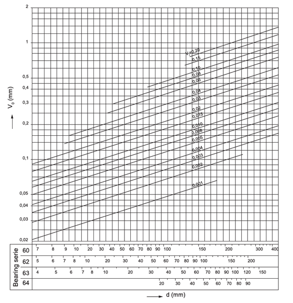
Fig. 7.4
7.3 Roller bearings materials
7.3.1 Materials of bearing rings and rolling bodies
For locations with a risk of damage in the area of rolling contact due to passage of electric current, bearings with ceramic insulation coating of the outer ring can be supplied.
If there are special requirements for material, design or use of bearings, information is available at the ZKL's technical an consultancy centre.
Semiproducts
Besides economic criteria, a semiproduct for production of roller bearings and rolling bodies has to comply with technological requirements in terms of proper course of fibres and proper distribution of carbidic phases. For the economic reason and also due to convenient passage of fibres, the most convenient is using a tube semiproduct that is cold rolled to final shape prior to thermal processing. In this way, the majority of the bearing assortment with increased basic durability is produced with the identification “NEW FORCE“.Through-hardening steels
Majority of standard produced ZKL roller bearings are made of through-hardening steels designed for production of roller bearings. Those are carbon – chromium steels with an approximate content of 1% carbon and 1.5% chromium, complying with the international standard ISO 683-17 “Heat-treated steels, alloy steels and free-cutting steels, Part17: Steels for rolling bearings”. After thermal treatment, material has the same structure and hardness throughout the component section. After performed martensitic or bainite hardening and subsequent yielding, the hardness of final surfaces is 58 to 65 HRC.Depending on the type, the highest service temperature of 120°C to 200°C is recommended for standard ZKL roller bearings. The maximum temperature for using the bearings depends on heat treatment of bearing components. For operation at temperatures to 250°C, bearing components can stabilize in a special heat treatment process. In case of thermal stabilization for operation at higher temperatures, the hardness of components reduces significantly, and thus also the dynamic load capacity of the bearings. If long-term operation above 250°C is required, we recommend bearings from high alloy steels designed for high temperatures.
Case hardening steels
After saturation with carbon and hardening, bearing components feature hard surface and simultaneously also tough core. They are used for production of bearings that are loadable with big strokes, locations with big overlap or alternatively for locations with a possibility of contaminated lubrication.Corrosion-proof steels
These steels are used for bearings intended for operation in oxidizing environment, for instance for aviation technology or food processing industry.Steels for high temperatures
These materials are used for bearings operating permanently at temperatures over 250°C whilst maintaining hardness and standard service properties, e.g. in aircraft engines.Steels for surface hardening
These steels offer convenient combination of hardened tough orbit with tough section core. They are used mainly in large bearings, or bearings with clamp flanges which are contained in bearing rings.7.3.2 Materials for production of cages
The basic quality of materials used for production of cages is good abrasion resistance and slip properties along with sufficient ductility.
Pressed steel cages
They are pressed from low carbon steels that ensure accuracy of final cage shape, as well as sufficient ductility. To improve slip properties and abrasion resistance, the surface of pressed cages is chemically and thermally treated. They suit typical temperature regimen of bearing operation up to 300°C.In smaller bearings sizes, pressed cages are even made of brass sheet.
Massive brass cages
They are made in routing from roughened or spun semiproducts. Service temperature should not exceed 250°C.Massive steel cages
In justified cases they are an alternative to brass massive cages. Service temperature may range up to 300°C. The surface of the cage can be chemically and thermally treated.7.3.3 Other materials
Polymers
Polymers, usually of polyamide 66 reinforced with glass fibres, are used mainly for production of cages and cage guide rings of double row spherical roller bearings of CJ design. Service operation of these components should not exceed 120°C in the long term with the use of common lubricants, 150°C in the short term (within 10 hours), and 170°C in peaks (within 20 minutes). Usefulness of bearings with polyamide components at lower temperatures is, with regard to polyamide elasticity loss, up to the temperatures of -40°C.Ceramic materials
Are used mostly to prevent bearings from damage by passage of electric current, either in form of thermally layered coats on the surface of the outer or inner ring, alternatively by using rolling ceramic bodies. Use of rolling bodies from ceramic material is justified even in special high-revolution bearings.Other
Materials of contact seals are selected so as their thermal and degradation resistance suited the selected use.7.4 Cages
Cage has the below functions in a roller bearing: Distributes rolling bodies uniformly around the circumference and prevents their mutual contact which reduced friction in the bearing. It prevents slippage of rolling bodies in the bearing and falling rolling bodies out of separable bearings during their assembly.
In terms of design and materials, cages are divided in pressed (Fig. 7.5) and massive (Fig. 7.6).
Pressed cages are made mostly by pressing from steel or brass sheet, and usually are used in dimensionally smaller up to medium bearings. Comparing to massive cages, their advantage is lower weight.
Massive cages are made of steel, brass, bronze, light metals or plastics in various designs. Metal cage materials are used whenever increased requirements are imposed on the rigidity of the cage, and the bearing is designed for higher service temperatures. Cages in bearing run radially on rolling bodies which is the most common way, or on collar of one of the bearing rings (Fig. 7.7).
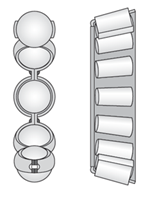 Fig. 7.5 |
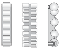 Fig. 7.6 |
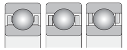 Fig. 7.7 |
Massive polymer cages are made in injection moulding. The injection moulding technology allows to production such cage shapes that enable designing bearings with high load capacity. Elasticity and low polyamide weight applies positively in shock stress of bearings, high acceleration and deceleration. Polyamide cages feature good slip properties. During lubrication of bearings with oil, the additives contained in the oil may affect negatively the service life of the cage.
Cages made of phenological resin are light but not suitable to high temperatures. They however feature good resistance to centrifugal forces. They are typically use in accurate ball bearings with angular contact.
Journal cages are made of steel; the condition is use of holy rolling bodies (Fig. 7.8). Journal cages are used mainly in large bearings
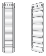
Fig. 7.8
Cageless bearings, i.e. with full number of rolling bodies, are used rarely - only in some types of bearings, e.g. single row roller bearings.
In texts to individual design bearing groups the section dedicated to cages always states an overview of cages made in the general design, and delivery option of bearings with cages in different designs.
7.5 Covers and seals
Bearings with covers on one or both sides are made with cover sheets (Z, 2Z, ZR, 2ZR – Fig. 7.9), or with contact seal ((RS, 2RS, RSR, 2RSR – Fig. 7.10). Cover sheets create contact-free sealing. In Z or 2Z version, the fitting for cover sheet is on the inner ring; ZR or 2ZR variants have cover sheet adhered to the smooth collar of the inner bearing ring.
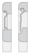 Fig. 7.9 |
 Fig. 7.10 |
The seal consists of sealing rings of nitrile rubber vulcanized on metal reinforcements that form an efficient contact seal in a design with rounded fitting on the inner ring (RS, 2RS), or in a design with contact on the smooth collar of the inner ring (RSR, 2RSR).
Covers and sealing rings are fastened in the outer ring recess, and are not detachable.
Bearings in basic design are filled with a quality plastic lubricant with temperature range between -30°C and + 100°C, in the short term even up to + 120°C. Filler of plastic lubricant usually ensures greasing throughout the service life in normal service conditions. Bearings in this design cannot be additionally greased.
7.6 Identification of roller bearings
Bearing is designated by basic identification and extension expressing the difference between this bearing and the standard version bearing. Identification of bearings contains numerical and literal characters that determine the type, size and design of the bearing. Overview of symbols and their order is based on the scheme shown in figure 7.11.
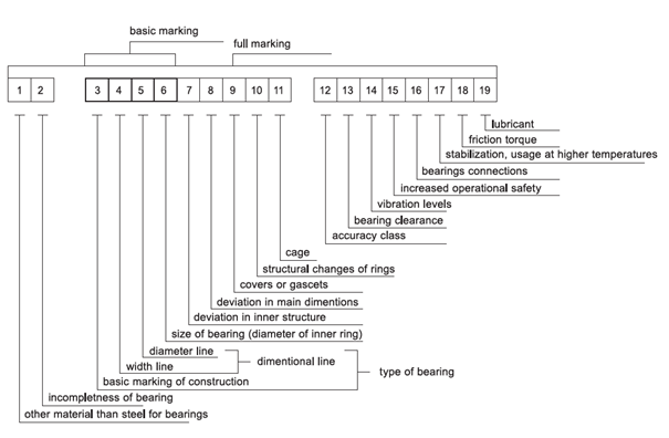
Fig. 7.11
7.6.1 General bearing version
Bearings with hole diameter d < 10 mm:
Figures separate with fraction line or the last digit states directly the nominal hole dimension in mm, e.g. 619/2, 624.Bearings with hole diameter d = 10 up to 17 mm:
double issue 00 identifies the hole d = 10 mm, e.g.: 620001 d = 12 mm, e.g. 51101
02 d = 15 mm, e.g. 3202
03 d = 17 mm, e.g. 6303
Exception in designation are single row ball bearings of separable type E and BO where the double issue states directly the hole diameter in mm, e.g.: E17.
Bearings with hole diameter d = 20 mm up to 480 mm
Hole diameter is quintuple of the last double issue, e.g. bearing 1320 features hole diameter d = 20 x 5 = 100 mm.Exceptions are bearings with hole diameter d = 22, 28 a 32 mm where the double issue separated with fraction line stated directly the diameter of hole in mm, e.g. a320/32AX, and some bearing types, such as e.g. separable single row ball bearings of E type, and single row ball bearings of NG type where the double or triple issue states directly the hole diameter in mm, e.g.: E20, NG160.
Bearings with hole diameter d > 500 mm:
The last double issue or triple digit separated with fraction line states directly the hole dimension in mm, e.g. 230/530M, NU29/1060.
7.6.2 Full identification of bearings
Meaning of supplementary characters
The following part states, in accordance with full designation, an overview and meaning of supplementary characters used. The digit in the bracket stated with individual groups corresponds with the position number in the scheme. The scheme also states positions in full naming of the bearing that us separated with a gap. Other characters are written together without a gap. Characters for extension of designation that mean a digit are separated with a dash from the basic designation, e.g. 6305-2Z.The meaning of supplementary characters for design variances of different bearing types is described in relevant chapters of the chart section of the catalogue.
Supplementary characters before basic designation
Other material than common steel for roller bearings (1)
C – rolling bodies from ceramics – e.g. C B7006CTAHAA – high speed steel, e.g.: HSS 6215
X – corrosion resistant steel, e.g.: X 623
T – case hardening steel, e.g.: T 32240
Bearing incompleteness (2)
R – Separable bearing without detachable ring, e.g. R NU206 nebo R N310
E – separate shaft ring or axial ball bearing, e.g. E 51314
W – separate body ring of axial ball bearing, e.g. W 51414
K – cage with rolling bodies e.g.: K NU320
Supplementary characters behind the basic designation
Difference in inner design (7)
A – single row angular-contact ball bearings with contact angle α = 25°, e.g. B7205ATB P5– single row tapered bearings with higher load capacity and higher limit revolution frequency, e.g. 30206A
– axial ball bearings with higher limit revolution frequency, e.g. 51,105A
AA - single row angular-contact ball bearings with contact angle α = 26°, e.g. B7210AATB P5
B – single row angular-contact ball bearings with contact angle α = 40°, e.g. 7304B
– single row tapered bearings with contact angle α = 17°, e.g. 32315B
BE - single row angular-contact ball bearings with contact angle α = 40°, in new design, e.g. 7310BETNG
C – single row angular-contact ball bearings with contact angle α = 15°, e.g. 7220CTB P4
– double row spherical roller bearings in new design, e.g. 22216C
CA – single row angular-contact ball bearings with contact angle α = 12°, e.g. B7202CATB P5
CB – single row angular-contact ball bearings with contact angle α = 10°, e.g. B7206CBTB P4
D – single row ball bearing of type 160 with higher load capacity, e.g. 16004D
E – single row ball bearings with higher load capacity, e.g. NU209E
– double row spherical roller bearings with higher load capacity, e.g. 22215E
– Axial spherical roller bearings with higher load capacity, e.g. 29416E
Difference in main dimensions (8)
X – Change in main dimensions, established by new international standards, e.g. 32028AXCovers (9)
RS – seal on one side, e.g. 6304RS-2RS – seal on both sides, e.g. 6204-2RS
RSN – seal on one side and snap ring groove on the outer ring on the opposite side than the seal, e.g. 6306RSN
RSNB - seal on one side and snap ring groove on the outer ring on the same side as the seal, e.g. 6210RSNB
-2RSN - seal on both sides and snap ring groove on the outer ring, e.g. 6310-2RSN
RSR – seal on one side, adhering to the smooth inner ring collar, e.g. 624RSR
-2RSR –těsnění na obou stranách přiléhající na hladký nákružek vnitřního kroužku,
např. 608-2RSR
Z – Cover sheet on one side, e.g. 6206Z
-2Z – Cover sheet on both sides, e.g. 6304-2Z
ZN – seal on one side and snap ring groove on the outer ring on the opposite side than the cover sheet, e.g. 6208ZN
ZNB – cover sheet on one side and snap ring groove on the outer ring on the same side as the cover sheet, e.g. 6306ZNB
-2ZN – cover sheets on both sides and snap ring groove on the outer ring, e.g. 6208-2ZN
ZR – cover sheet on one side, adhering to the smooth inner ring collar, e.g. 608ZR
-2ZR – cover sheets on both sides, adhering to the smooth inner ring collars, e.g. 608-2ZR
Design change of bearing rings (10)
K30 – Tapered hole, taper ratio 01:30:00, e.g. 24064K30M
N – snap ring groove on the outer ring, e.g. 6308N
NR – snap ring groove on the outer ring, and inserted snap ring, e.g. 6310NR
NX – snap ring groove on the outer ring, dimensions of which do not comply with ČSN 02 4605, e.g. 6210NX
D – split inner ring, e.g. 3309D
W33 – groove and lubrication holes on the outer ring circumference, e.g. 23148W33M
O – lubrication slots on outer ring fillet of the bearing , e.g. NU1014O
Cage (11)
J – cage pressed from steel plate, guided on rolling bodies e.g.: 6034J
J2 – cage pressed from steel plate, guided on rolling bodies. New design of single row tapered bearings, e.g. 30206AJ2
Y – cage pressed from brass sheet, guided on rolling bodies e.g.: 6001Y
F – massive steel cage, guided on rolling bodies e.g.: 6418F
L – massive light metal cage, guided on rolling bodies e.g.: NG180L C3S0
M – massive brass or bronze cage, guided on rolling bodies e.g.: NU330M
T – massive textite cage, guided on rolling bodies e.g.: 6005T
TN – massive cage of polyamide or similar plastic, guided on rolling bodies e.g.: 6207TN
TNG - massive cage of polyamide or similar plastic, stiffened by glass fibres, guided on rolling bodies e.g.: 2305TNG
Cage design (stated characters are always used in combination with cage material characters).
A – cage guided on outer ring, e.g. NU226MA
B – cage guided on inner ring, e.g. B7204CATB P5
P – massive window cage, e.g.: NU1060MAP
H – open single-piece cage, e.g.: 629TNH
S – cage with lubrication slots, e.g.: NJ418MAS
R – silver-plated cage, e.g.: 6210MAR
V – bearing without cage with full number of rolling bodies, e.g. NU209V
Accuracy level (12)
P6 – higher accuracy level than normal, e.g. 6322 P6
P5 – higher accuracy level than P6, e.g. 6201 P5
P5A – higher accuracy level than P5 in some parameters, e.g. 6006TB P5A
P4 – higher accuracy level than P5, e.g. B7204CBTB P4
P4A – higher accuracy level than P4 in some parameters, e.g. B7205CATB P4A
P2 – higher accuracy level than P4, e.g. B7200CBTB P2
P6E – higher accuracy level for rotary electrical machines, e.g. 6204 P6E
P6X – higher accuracy level for single row tapered bearings, e.g. 30210A P6X
SP – higher accuracy level for roller bearings with tapered hole, e.g. NN3022K SPC2NA
UP – higher accuracy level such as SP for roller bearings with tapered hole, e.g. N1016K UPC1NA
Clearance (13)
– normal clearance (is not designated), e.g. 6204
C3 – bigger clearance than normal, e.g. 6310 C3
C4 – bigger clearance than C3, e.g. NU320M C4
C5 – bigger clearance than C4, e.g. 22330M C5
NA – radial clearance in bearings with incommutable rings (is indicated always behind the radial clearance group), e.g. NU215 P63NA
R... – radial clearance in non-standardised range (range in µm) , e.g. 6210 R10-20
A... – axial clearance in non-standardised range (range in µm) , e.g. 3210 A20-30
Noise level (14)
C06 - reduced noise level lower than C6, e.g. 6205 C06
C66 - reduced noise level lower than C06, e.g. 6205 C66
Specific values for C06 and C66 are determined based on an agreement between customer and supplier.
Note: Bearings in accuracy level P5 and higher feature noise level within C6.
Increased operational safety (15)
Combining characters (12-15)
P6 + C3 = P63 e.g. 6211 P63
P6 + C8 = P68 e.g. 16002 P68
C3 + C6 = C36 e.g. 6303-2RS C36
P5 + C3 + C9 = P539 e.g. 6205MA P539
P6 + C2NA + C6 = P626NA e.g. NU1038 P626NA
Bearing association (16)
Designation of associated pair, triplet or quaternion of bearings consists of characters expressing arrangement of bearings and of characters defining the inner clearance or prestress of associated bearings.
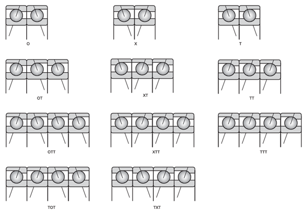
Fig. 7.12
Apart from characters stated in the chart the U character is used to identify that relevant bearings can be associate universally, example of designation B7003CTA P4UL.
Inner clearance or prestress
A – Association of bearings with clearances, e.g. 7305OA
O – Association of bearings without clearances, e.g. 7305 P6XO
L – Association of bearings with small prestress, e.g. B7205CATB P4UL
M – Association of bearings with medium prestress, e.g. B7204CATB P5XM
S – Association of bearings with big prestress, e.g. B7304AATB P4OS
Stabilisation for operation at higher temperature (17)
S0 – for service temperature up to 150 °C
S1 up to 200 °C
S2 up to 250 °C
S3 up to 300 °C
S4 up to 350 °C
S5 up to 400 °C
Example of designation NG160LB C4S3
Friction torque (18)
JUA – bearings with defined friction torque at start-up 632 JUA
JUB – bearings with defined friction torque at after-running, e.g. 623 JUB
Plastic lubricant (19)
TL – lubricant for low service temperatures from -60 °C to +100 °C
example of designation 6302 2RSTL
TM – lubricant for medium service temperatures from -35 °C to +140 °C
example of designation 6204 2ZRTM
TH – lubricant for high service temperatures from -30 °C to +200 °C
example of designation 6202 2ZTH
TW – lubricant for both low and high service temperatures from -40 °C to +150 °C
example of designation 6310 2ZC4TW
Note: The TM marking need not be stated on bearings and containers.
Bearings by special technical conditions
TPF – bearings made by special technical conditions agreed with customer, e.g. bearing 6205MA P66 by technical terms TPF 11142-71 is designated as follows: 6205MA P66 TPF 142.
TPFK - bearings by special technical terms agreed with customer which have high number of characters stating changes against the basic version. In this case, basic characters are replaced with designation TPFK containing relevant number of technical terms, e.g. bearing NU1015 made by technical terms. TPFK 11137-70 is designated as NU1015 TPFK137.
Bearings by special drawing documentation PLC
PLC ABC-DE.F (designation structure until 2012)
PLC – identification of special roller bearing
A – design assembly
0 – single row ball bearings
1 – double row ball bearings:
2 – axial ball bearings
3 – Not completed.
4 – single row roller, spherical-roller and needle bearings
5 – double and multirow roller, spherical-roller and needle bearings
6 – single row, double row and four row tapered bearings
7 – special double row bearings
8 – assembly units and separate parts
9 – axial roller, spherical-roller, tapered and needle bearings
BC – dimensional assembly – two digit characters
DE – ordinal number within dimensional assembly – two digit characters
F – difference in design - one digit or combination of numerical character and letter
Due to extending the assortment of special bearings, it was decided in 2013 to change the structure of designating special bearings: Upon the establishing of a new system, the designation on already produced bearings will not be changed.
PLC AB-CD-EF.G (designation structure since 2013)
PLC – identification of special roller bearing
A – design assembly
1 – ball bearings
2 – axial ball bearings
3 – roller bearings
4 – axial roller bearings
5 – needle bearings
6 – spherical-roller bearings
7 – axial spherical-roller bearings
8 – tapered bearings
9 – axial tapered bearings
0 – other bearings and mounting assemblies
B – number of rolling units or bearings in mounting assemblies
CD – dimensional assembly – two digit characters
EF – ordinal number within dimensional assembly – two digit characters
G – difference in design - one digit or combination of numerical character and letter
7.7 NEW FORCE bearings
In order to satisfy the needs of technically advanced customers, ZKL pays particular attention to technical development of products and investments in new technologies. The outcome of one of the recent key innovations is initiation of successive start up of production of ZKL bearings with higher quality standard with designation NEW FORCE.The NEW FORCE bearings represent a new generation of ZKL bearings. Launching of bearings brings customers higher durability of bearings, enhanced operational safety, prolonged maintenance intervals and thus substantial reduction of operating costs. NEW FORCE bearings are designed for extreme locations of transmissions, railway vehicles, presses, rolling mills, paper machines, pumps, machine tools, power engineering plants, polygraphic machines, etc.
As the first integrated new generation bearings, the radial spherical-roller bearings were launched on the market, double row tilting ball bearings, double row angular-contact ball bearings and axial ball bearings. The next phase of launching bearings of this standard was the production assortment of bearings with outer diameter over 400 mm.
The achieved parameters of NEW FORCE bearings are the result of ZKL development in the following areas:
- Material of roller bearing components
- Technology of bearing ring flaring
- Optimisation of inner construction
- Surface treatments of bearing components
The achieved results allowed ZKL to offer NEW FORCE roller bearings with high utility properties to their customers:
- high dynamic load capacity
- low friction
- reliability in the extreme operating conditions
High durability of bearings
Increase of dynamic load capacity by 8% to 25% brings increase of durability of bearings by 30% up to 110%, comparing to the up-to-now designs.
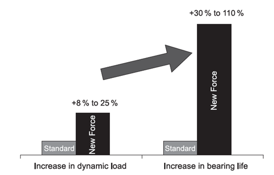
Fig. 7.13
Increase of dynamic load capacity allows customer to design construction with smaller dimensions to transfer the same load. Thus ZKL brings to their customer an opportunity to reduce total price of the equipment, and achieve power savings during operation.
Use of quality bearing material
Key quality parameters of steel and its processing affect the service properties of bearing, i.e. resistance to fatigue damage, abrasion resistance and dimensional stability. These are:
- chemical composition and heat treatment
Selection of the type of bearing steel and optimisation of heat treatment conditions is conducted by the dimension of the component. The heat treatment processing technology of NEW FORCE bearings ensures stabile hardness values of bearing components in the entire section. Spherical-roller bearing components are heat treated to ideal material structure and hardness that enable using of the bearings at service temperatures to 200 °C. The final material structure ensures dimensional stability of bearing components throughout their service life. - Content of non-metal intrusions - micropurity
Reduction of content of non-metal intrusions is the key quality parameter in the bearing steel metallurgy development. In production of bearings, ZKL utilises bearing steel with minimum oxygen content. - Type of semiproduct
The quality of bearing and production economics are affected also by selection of the semiproduct type. The level of forming and positive angle of forming fibre contact towards the orbit are the parameters that positively increase resistance of the NEW FORCE bearings against fatigue damage.
Technology of bearing ring flaring
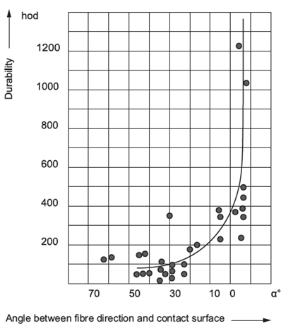
Fig. 7.15
Optimised design and inner geometry
This brings reduced noise level and higher accuracy of bearing run, as well as extended durability of bearings.
Special surface treatment
Bearings NEW FORCE +
Optimisation of the shape of rolling surfaces brings improved dynamic load capacity of bearings and thus also significant extension of bearings' durability. Development of the NEW FORCE+ generation is associated with the introduction of new calculation methods in the structure of bearings based on MKP and production upgrade by introducing numerically controlled machines that enable achieving final shapes of functional surfaces with modified geometry.
With regard to the fact that the entire design optimisation and production process of modified parts is unique for every bearing application, the NEW FORCE+ bearing generation is not designed to be launched in the standard production program of ZKL. The bearings will be manufactured upon request for extreme locations for selected OEM customers.