11.1 Main types of damage
Examples of main types of roller-contact bearing damage are illustrated in the following figures.Flaking of the surface
Unacceptable tearing off of material due to thermal overloading of the bearing is shown in fig. 11.1 and 11.2.
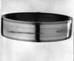 Fig. 11.1 |
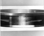 Fig. 11.2 |
Typical fatigue effect – pitting, which forms on the bearing races, is shown on fig. 11.3 and 11.4. This damage is the result of cyclical loading of bearing components and is caused by normal fatigue of the material. The first cracks emanate from miniature non-homogeneities in the material at a particular depth below the surface. They are often, however, caused by overloading, insufficient lubrication, or other operating influences. Their timely identification can better help analyse and eliminate the cause. The figures illustrate unacceptable wear.
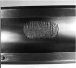 Fig. 11.3 |
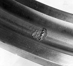 Fig. 11.4 |
Depressions and pressure damage
Damage to bearing races caused by indelicate installation (fig. 11.5) and shallow depressions in the orbit caused by beading of solid impurities during bearing operation (fig. 11.6). The extent of damage in both illustrated cases is unacceptable and may form the initial site of progressive fatigue damage – pitting. Damage to orbits caused by improper installation are usually easily discernible because they are located within the pitch of the roller elements. Pressure damage caused by stationary overloading or by equipment vibrations when transporting over long distances , e.g. during shipping, also present a danger.
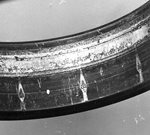 Fig. 11.5 |
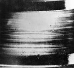 Fig. 11.6 |
Abrasion
Ball glazing due to overloading and lubrication failures (fig. 11.7) and abrasion of the race due to spinning within the seat (fig. 11.8). The condition in both cases is unacceptable.
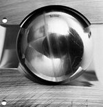 Fig. 11.7 |
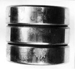 Fig. 11.8 |
The formation of grooves and craters due to the passage of electric current
Damage to the ball (fig. 11.9) and the orbit (fig. 11.10) by the passage of electric current through the roller contact. This type of damage is unacceptable. This forms when sparking occurs over a thin layer of lubricant. Burned-out cratering forms on such sites and are a source of bearing vibration and increased noise. This type of damage in motor housings and other roller-contact seats of rail vehicles with electrical traction are prevent, for example, by the use of bearings with an insulation layer on one of the rings and by the use of hybrid bearings with ceramic balls.
 Fig. 11.9 |
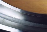 Fig. 11.10 |
Wear
Wear on the rolling surfaces of rollers (fig. 11.11) and races (fig. 11.12) are caused by lubrication failure without flaking of material. Such damage may occur primarily in areas, where maintenance of the lubricating film is hindered, such as bearing ring faces or on roller faces. Undesirable wear may also occur due to slippage of rolling elements towards the bearing rings. Wear is characterized by traces of seizing and slippage, which is often accompanied by brownish spots on the orbit. This is unacceptable wear.
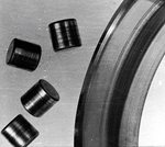 Fig. 11.11 |
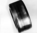 Fig. 11.12 |
Corrosion
The first picture (fig. 11.13) shows traces of acceptable contact corrosion on the orbit and the second (fig. 11.14) show inner ring corrosion. Corrosion resulting from inadequate protection against moisture or the use of an unsuitable lubricant is always impermissible. Areas affected by rust formation may progressively become initial sites of flaking of operating surfaces, which can lead to deteriorated operating precision and decreased bearing durability. Corrosion occurs when atmospheric moisture condenses, which can occur under improper storage conditions. Contact corrosion is caused by very weak oscillations or vibrations of loose components, which can lead to serious bearing damage and thus prevent their further use.
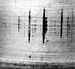 Fig. 11.13 |
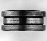 Fig. 11.14 |
Cage damage
Under normal operating conditions, the roller-contact bearing cage is stressed little. Damage primarily occurs due to poor lubrication. When lubrication is inadequate, cage wear first occurs on the surfaces in contact with rolling elements or with guiding surfaces of bearing rings. The first picture (fig. 11.15) shows deep cage pocket wear from contact with the roller with traces of flaked material. This extent of damage is impermissible. The second picture (fig. 11.16) shows permissible glazing of the guide diameter of the solid bronze ball bearing cage.
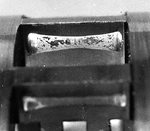 Fig. 11.15 |
 Fig. 11.16 |